Mitsubishi Lancer Evolution 8. Manual - part 92


  Index      Mitsubishi     Mitsubishi Lancer Evolution 8 - service repair manual


Search            


Content   ..  90  91  92  93   ..


Mitsubishi Lancer Evolution 8. Manual - part 92


CLUTCH - HOW TO FOLLOW THIS MANUAL

21-3

These symbols/letters correspond with symbols/letters in
removal / fitting / dismantling / assembling order

Explains procedure / precautions
required when removing / fitting /
dismantling / assembling.
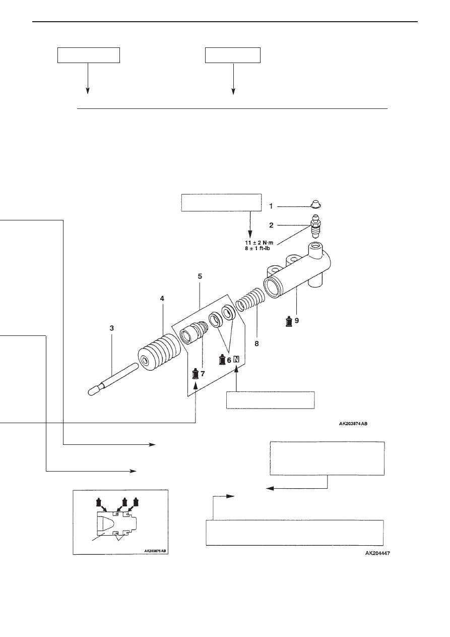
Piston       Piston caps

Dismantling Order

1.Lock pin
2.Interlock plate
3.Control finger
4.Pin

>>A<< 5.Return spring

Denotes part which cannot
be re-used

Denotes tightening torque

Page number

Section title

21-8

CLUTCH RELEASE CYLINDER

Clutch Release Cylinder

Dismantling / Assembling

Key Point for Assembling

>>A<< Fitting piston assembly
Smear brake fluid on inner surface of release cylinder and all over
piston / piston caps, then insert piston assembly into release cylinder.

CLUTCH - SPECIFICATIONS

21-4

Specifications


M1212000200137

Item

Specification

Type

Dry single plate type

Clutch disc

Facing dimensions (mm)

240 x 160

Type

Diaphragm spring pull type

Clutch cover

Set load (N)

9320

Clutch control method

Hydraulic

Maintenance Standards


M1212000300101

Item

Limit (mm)

Clutch disc facing rivet sinkage

0.3

Clutch diaphragm spring tip height variation

0.5

Tightening Torques


M1212001800109

Item

Tightening Torque  (N

m)

Clutch tube flare nut

15 

±

 2

Clutch fluid line bracket bolt

18 

±

 3

Clutch release cylinder fitting bolt

18 

±

 3

Clutch release fork shaft fitting bolt

9.8 

±

 2.0

Clutch release cylinder union bolt

22 

±

 2

Clutch cover bolt

18 

±

 3

Clutch release cylinder air breather

11 

±

 1

Lubricants


M1212000400119

Item

Brand

Release fork and release cylinder push rod contact surfaces
Release fork and release shaft sliding section
Release fork and release bearing contact surfaces

0101011 or equivalent

Whole of piston and piston caps
Inside of release cylinder

4 or equivalent

CLUTCH - CLUTCH

21-5

CLUTCH

Removal / Fitting

RemovalOrder

Removal Order (continued)

1. 

Clutch fluid line bracket   

>>C<<

11. 

Sealing cap

2. 

Clutch fluid line

12. 

Release fork shaft

3. 

Union bolt

13. 

Support spring (L)

4. Union

14. 

Washer

5. Gaskets

>>B<<

15. 

Release 

fork

>>E<<

6. Valve 

plate

>>A<<

16. 

Bushes

>>E<<

7. 

Valve plate spring

17. 

Clutch release bearing

>>D<<

8. 

Clutch release cylinder

18. 

Washer

9. 

Clutch cover

19. 

Support spring (R)

10.

Clutch disc

20. 

Release fork boot

CLUTCH - CLUTCH

21-6

KEY POINTS FOR FITTING

>>A<< Fitting bushes
Press fit bushes as far as position on release fork
shown in drawing.

>>B<< Fitting release fork
Apply grease on release fork at locations shown in
drawing.
Grease
Brand: 0101011 or equivalent

>>C<< Fitting sealing cap
Press fit sealing cap as far as position shown in
drawing, making sure it is not tilted.

>>D<< Fitting clutch release cylinder
Apply grease on release fork at location shown in
drawing.
Grease
Brand: 0101011 or equivalent

Bushes 

Release fork


Content   ..  90  91  92  93   ..