Mitsubishi Lancer Evolution 8 MR. Manual - part 15


  Index      Mitsubishi     Mitsubishi Lancer Evolution 8 MR - service repair manual 2004 year


Search            


Content   ..  13  14  15  16   ..


Mitsubishi Lancer Evolution 8 MR. Manual - part 15


INTAKE – EXHAUST – VEHICLE SERVICING

15-2

1) Wastegate actuator misoperation
2) Wastegate valve misoperation
3) Wastegate actuator rubber hose detachment, cracking.

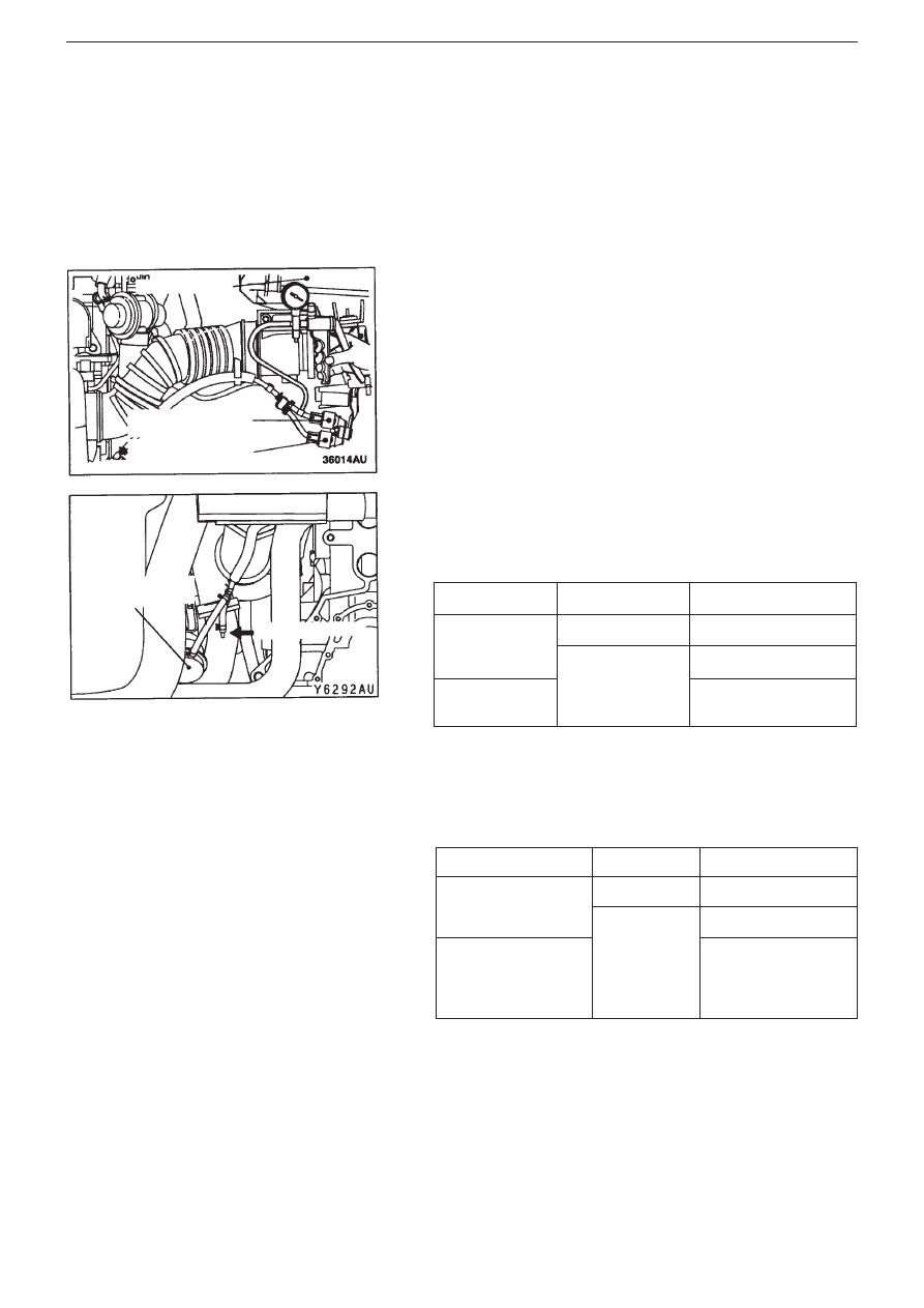
2. Boost pressure control system inspection <6M/T>
Note
The driving test, which is done with the throttle fully open,
must be done in a safe place with two people in the vehicle.
The person sitting in the passenger seat should take the
reading of the values on the pressure gauge.
(1) Remove hose (black) from No.1 wastegate solenoid valve, then

connect a three-way coupling between the hose and the
solenoid valve.

(2) Connect a hand vacuum pump to the three-way coupling.

(3) Remove boost hose from the wastegate actuator control boost

nipple on the air outlet fitting, and fit a plug over the nipple.

(4) Apply a vacuum whilst covering and releasing the tip of the

hose to check the vacuum condition.

(5) Ignition switch to “LOCK” (OFF) position.
(6) Remove wastegate solenoid valve connector.
(7) Apply a vacuum whilst covering and releasing the tip of the

hose, to check the vacuum condition (stop the hose tip with a
plug when driving).

Note
When vacuum condition is not normal, it may be assumed that
there is a  problem with the wastegate actuator, wastegate solenoid
valve, or hose.

Engine condition

Boost hose tip

Normal condition

Stop (ignition
switch: “ON”
position)

Released

Vacuum leaks

Covered

Vacuum is maintained

Idle running after
warming up.

Vacuum leaks

Engine condition

Boost hose tip

Normal condition

Stop (ignition switch:
“ON” position)

Released

Vacuum leaks

Covered

Vacuum is maintained

Accelerating with
throttle full open in
2nd gear (at least
3500rpm)

Vacuum leaks

Air cleaner

No.1 Wastegate
solenoid valve
No.2 Wastegate
solenoid valve

Wastegate
actuator

Boost hose

INTAKE, EXHAUST – AIR CLEANER

15-3

Air Cleaner

Removal and Fitting

Note

The parts marked with a 

symbol are plastic components which contain recycled paper. Please note the following:

When fixing or removing, or after fitting parts, be careful not to knock or apply force to these components.

When assembling, fix the air cleaner body ASSY securely to the air cleaner cover using the clamp on the body.

Remarks
Parts marked with a 

symbol use plastic that may contain recycled paper, so when scrapped are burnable.

Removal procedure
1. Battery
2. Air duct
3. Air flow sensor connector
4. Air cleaner assembly
5. Air flow sensor
6. Gasket
7. Air cleaner cover
8. Air cleaner element
9. Air cleaner body assembly
10. Vacuum hose

•   Air pipe E, air hose D, air by-pass valve

assembly, air by-pass hose.

•    Oil level gauge assembly
11. Air intake hose
12. Wastegate solenoid valve connector
13. Vacuum hose connection
14. Wastegate solenoid valve assembly
15. Air cleaner bracket 

<Memo>

SECTION 22

MANUAL TRANSMISSION

CONTENTS

General........................................................1

Troubleshooting .........................................1

General

The following troubleshooting items have been changed along with the changes to the wiring. Troubleshooting points other than

those mentioned below remain unchanged, and are the same as on the existing Lancer Evolution VII/VIII.

Troubleshooting

1. Diagnosis Code List

MANUAL TRANSMISSION – GENERAL, TROUBLESHOOTING

22-1

Diagnosis code no.

Diagnosis item

Page ref.

12

Power supply voltage (valve power supply) system

Broken wire or short

22-2

21

Vehicle wheel speed sensor <FR> system <ACD fitted vehicles>

Broken wire or short

22-3

22

Vehicle wheel speed sensor <FL> system <ACD fitted vehicles>

Broken wire or short

22-3

23

Vehicle wheel speed sensor <RR> system <ACD fitted vehicles>

Broken wire or short

22-3

24

Vehicle wheel speed sensor <RL> system <ACD fitted vehicles>

Broken wire or short

22-3

25

Abnormal diameter tyres <ACD fitted vehicle>

22-5

26

Vehicle wheel speed sensor system (output signal abnormal) <ACD fitted vehicles>

22-6

41

TPS system

Broken wire or earthing

22-7

42

Short

22-7

45

Pressure sensor system

Broken wire or earthing

22-8

46

Earth wire broken

22-8

47

Abnormal power supply

22-9

51

Longitudinal  G sensor system

Broken wire or short

22-10

52

Sensor malfunction

22-11

56

Lateral G sensor system

Broken wire or short

22-12

57

Sensor malfunction

22-13

61

Stop lamp switch system

Broken wire

22-14

62

ACD mode switch system

Sticking

22-15

63

Parking brake switch system

Short or failing to return

22-16

65

ABS monitor system <ACD+AYC fitted vehicles>

Broken wire or ABS failure

22-17

74

Proportional control valve <ACD> system

Broken wire or short

22-18

81

Electrical  pump relay system

Broken wire or short

22-18


Content   ..  13  14  15  16   ..