Mitsubishi Lancer Evolution 7. Manual - part 391


  Index      Mitsubishi     Mitsubishi Lancer Evolution 7 - service repair manual


Search            


Content   ..  389  390  391  392   ..


Mitsubishi Lancer Evolution 7. Manual - part 391


SWS -

Troubleshooting

54B-9

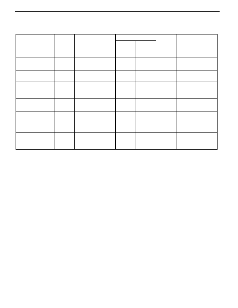
Input Signal Inspection Procedure Nos. by Function
When more than one SWS function fails at the same time, run checks based on the following table.

(The table lists only input signals and functions in which multiple faults can occur.)

Function

J-1

J-2

J-3

J-5

J-6

J-7

J-8

Driver’s door

All doors

Central locking
control

F

Power window control

F

Power window timer

F

F

Windshield wiper
and washer control

F

F

Rear wiper and

washer control

F

F

Headlamp control

F

Rear fog lamp control

F

Tail lamp control

F

Headlamp automatic
turn-off

F

F

F

Turn signal lamp
control

F

F

Hazard warning lamp
control

F

Room lamp control

F

F

F

SWS -

Troubleshooting

54B-10

INSPECTION PROCEDURE FOR TROUBLE SYMPTOMS

Inspection Procedure A-1

No communication with MUT-II

Probable cause

Either the ETACS-ECU power supply circuit system or the harness or connector

between the diagnosis connector and ETACS-ECU may be defective.

D

Harness or connector fault

D

ETACS-ECU fault

NG

Check the harness between ETACS-ECU and the body earth,

and repair if necessary.

NG

Repair

NG

Repair

OK

Replace ETACS-ECU.

NG

Check the harness between ETACS-ECU and diagnosis

connector.

NG

Repair

OK

Check the trouble

symptoms.

OK

Check the following connectors:

<L.H. drive vehicles> C-228, C-26, C-22

<R.H. drive vehicles> C-228, C-28, C-22

OK

Check the trouble

symptoms.

NO

Measure at the ETACS-ECU connector C-228.
D

Disconnect the connector and test on the junction box

side.

D

Continuity between terminal 56 and body earth.

OK : Continuity confirmed.

NG

Check the following connectors: C-228, C-08

YES

Is communication, by MUT-II, possible with other systems?

YES

Check ETACS-ECU battery power circuit system (Refer to

P.54B-33, Inspection Procedure K-1).

Is communication by MUT-II possible when the ignition switch

is ON?

NO

Check the MUT-II diagnosis circuit, and repair if necessary.

NOTE:

When failure is detected on the harness between ETACS-ECU and the body earth, check No. 3 terminal

(C-226) of ETACS-ECU as well. Repair, if required.

Inspection Procedure B-1

Lights left ON reminder warning function not working

normally.

Probable cause

The ETACS-ECU controls the headlamp automatic cut-off function based on input

signals from the following switches.
D

Ignition switch (IG1)

D

Driver’s door switch

D

Tail lamp switch

D

Headlamp switch

D

Driver’s door switch fault

D

Column switch fault

D

ETACS-ECU fault

D

Harness or connector fault

OK

Replace ETACS-ECU.

YES

Check the MUT-II input signals.
D

Ignition switch (IG1)

D

Driver’s door switch

D

Tail lamp switch

D

Headlamp switch

NG

Check the defective input circuit. (Refer to P.54B-7, Defects

Found by Input Signal Check).

Do all of the following functions operate when the ignition

switch is in the LOCK (OFF) position?
D

Central locking

D

Hazard lamps

NO

Check ETACS-ECU battery power circuit system (Refer to

P.54B-33, Inspection Procedure K-1).

SWS -

Troubleshooting

54B-11

Inspection Procedure C-1

Central door locking system not working at all.

Probable cause

A change in the input signal from the driver’s door lock actuator activates all the

door lock actuators, causing the ETACS-ECU to lock or unlock all the doors.

If the central locking is not working normally, the driver’s door lock actuator or

the ETACS-ECU may be defective.

D

Driver’s door lock actuator fault

D

ETACS-ECU fault

D

Harness or connector fault

NG

Repair

OK

Replace ETACS-ECU.

NG

Check the harness between ETACS-ECU and battery.

NG

Repair

OK

Check the trouble

symptoms.

OK

Check the following connectors: C-226, C-211, C-35, C-132

YES

Check the driver’s door lock actuator (Refer to GROUP 42 -

Doors).

NG

Repair

Do all of the following functions operate when the ignition

switch is in the LOCK (OFF) position?
D

Lights left ON reminder warning function

D

Hazard warning lamps

D

Room lamps

NO

Check ETACS-ECU battery power circuit system (Refer to

P.54B-33, Inspection Procedure K-1).

OK

Check the MUT-II input signals.
D

Driver’s door lock actuator

NG

Check the driver’s door lock actuator input circuit system

(Refer to P.54B-30, Inspection Procedure J-6).

Inspection Procedure C-2

Some doors not locking or unlocking.

Probable cause

The door lock actuator of the door(s) that are not responding may be defective.

D

Door lock actuator fault

D

Harness or connector fault

NG

Check the harness between ETACS-ECU and the door lock

actuator of the door(s) not responding, and repair if necessary.

OK

Check the trouble symptoms.

OK

Check the following connectors:

<L.H. drive vehicles>

<Driver’s door> C-227, C-110, C-213, C-226, E-08

<Passenger’s door> C-226, C-213, C-24, E-18

<Rear left door> C-226, C-216, D-12, E-12

<Rear right door> C-226, C-213, C-112, D-02, E-23

<R.H. drive vehicles>

<Driver’s door> C-227, C-24, C-28, C-213, C-226, E-08

<Passenger’s door> C-226, C-213, C-110, C-28, E-18

<Rear left door> C-226, C-213, C-28, C-133, D-12, E-12

<Rear right door> C-226, C-216, D-02, E-23

NG

Repair

Check the driver’s door lock actuator that are not responding

(Refer to GROUP 42 - Doors).

NG

Replace

SWS -

Troubleshooting

54B-12

Inspection Procedure D-1

Power windows not working at all.

Probable cause

Power windows are not operated with the power window

main switch.

The power window relay or the ETACS-ECU may be defective.

D

Power window relay fault

D

ETACS-ECU fault

D

Harness or connector fault

NG

Check the harness between the power window relay and the

fusible link (5), and repair if necessary.

NG

Repair

OK

Check the trouble

symptoms.

OK

NG

Check the following connectors:

C-224, C-210, C-35 (R.H.drive vehicles only), C-132

OK

Check power window relay (Refer to GROUP 42 - Door.)

NG

Replace

Check the MUT-II input signals.
D

Ignition switch (IG1)

NG

Check the ignition switch (IG1) input circuit system (Refer to

P.54B-26, Inspection Procedure J-2).

NG

Check and repair the harness between the power window

relay and the body earth.

NG

Repair

OK

Replace ETACS-ECU.

OK

Check the trouble

symptoms.

OK

Measure at the power window relay connector C-224.
D

Disconnect the connector and test on the junction box

side.

D

Continuity between terminal 3 and body earth.

OK : Continuity confirmed.

NG

Check the following connectors:

<L.H. drive vehicle> C-224, C-213, C-08

<R.H. drive vehicle> C-224, C-213, C-102

Measure at the power window relay connector C-224.
D

Disconnect the connector and test on the junction box

side.

D

Voltage between terminal 5 and the body earth.

OK : System voltage


Content   ..  389  390  391  392   ..