Mitsubishi Lancer Evolution 7. Manual - part 278
FRONT AXLE -
Drive Shaft
26-15
"
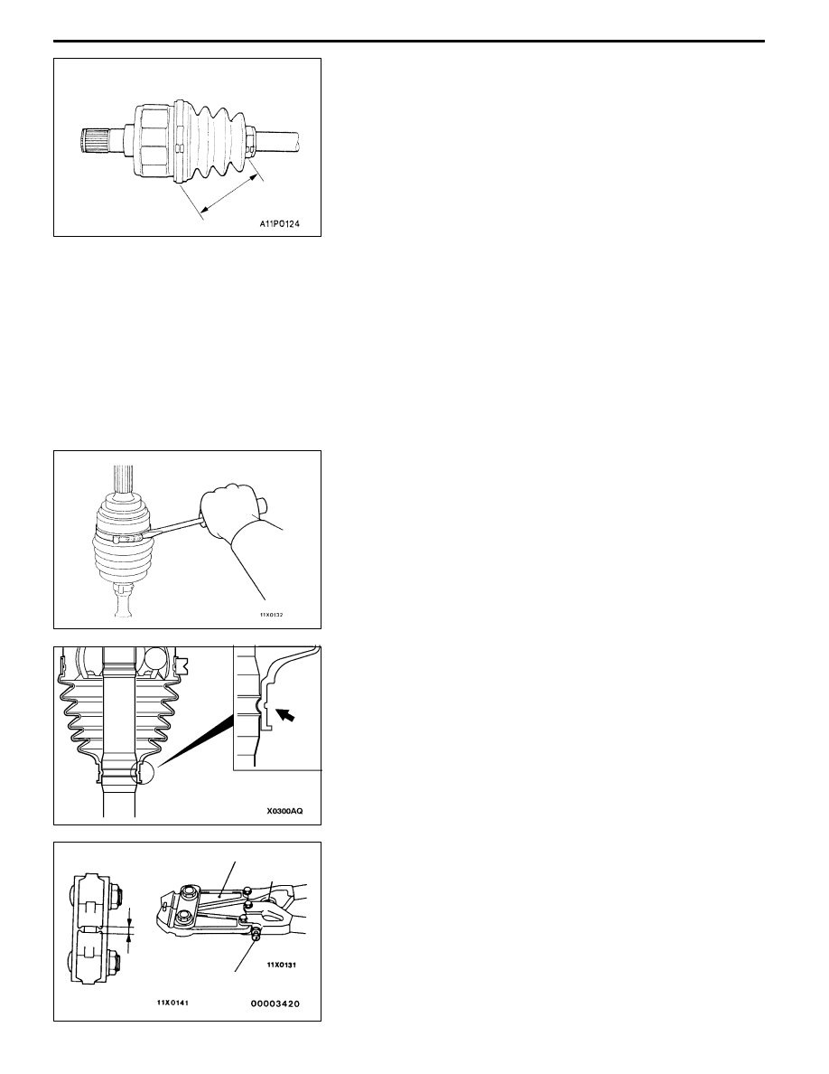
BA T.J. BOOT BAND (SMALL)/T.J. BOOT BAND
(LARGE) INSTALLATION
Set the T.J. boot bands at the specified distance in order
to adjust the amount of air inside the T.J. boot, and then
tighten the T.J. boot bands securely.
Standard value (A): 85±3 mm
INSPECTION
D
Check the drive shaft for damage, bending or corrosion.
D
Check the drive shaft spline part for wear or damage.
D
Check the spider assembly for roller rotation, wear or
corrosion.
D
Check the groove inside T.J. case for wear or corrosion.
D
Check the boots for deterioration, damage or cracking.
D
Check the dust cover for damage or deterioration.
B.J. BOOT (RESIN BOOT) REPLACEMENT
1. Remove the B.J. boot bands (large and small).
NOTE
The B.J. boot bands cannot be re-used.
2. Remove the B.J. boot.
3. Wrap a plastic tape around the shaft spline, and assemble
the B.J. boot band and B.J. boot.
4. Install the groove in the center of the small diameter
part of the resin boot by fitting to the groove of the shaft.
5. Turn the adjusting bolt on the special tool so that the
size of the opening (W) is at the standard value.
Standard value (W): 2.9 mm
<If it is larger than 2.9 mm>
Tighten the adjusting bolt.
<If it is smaller than 2.9 mm>
Loosen the adjusting bolt.
NOTE
(1) The value of W will change by approximately 0.7
mm for each turn of the adjusting bolt.
A
MB991561
Stopper
Adjusting bolt
W