Mitsubishi Lancer Evolution 7. Manual - part 277


  Index      Mitsubishi     Mitsubishi Lancer Evolution 7 - service repair manual


Search            


Content   ..  275  276  277  278   ..


Mitsubishi Lancer Evolution 7. Manual - part 277


FRONT AXLE -

Drive Shaft

26-11

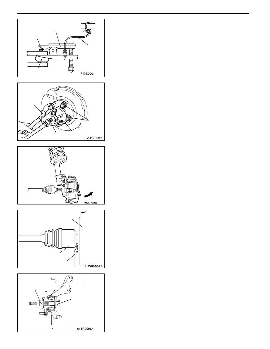
REMOVAL SERVICE POINTS

A

ATIE ROD END DISCONNECTION

Caution

1. Loosen the nut only; do not remove it from the ball

joint. Otherwise ball joint thread will be damaged.

2. The special tool should be suspended by a cord to

prevent it from coming off.

A

BDRIVE SHAFT REMOVAL

1. Use the special tools to push out the drive shaft from

the hub.

2. Withdraw the drive shaft from the hub by pulling the bottom

of the brake disc towards you, and then remove the hub

retaining bolts.

3. Remove the drive shaft from the transmission by the

following procedure.

Insert a pry bar between the transmission case and the

drive shaft, and then pry the drive shaft from the

transmission.
Caution

(1) Do not pull on the drive shaft; doing so will damage

the T.J.; be sure to use the pry bar.

(2) When pulling the drive shaft out from the

transmission, be careful that the spline part of

the drive shaft does not damage the oil seal.

(3) Do not apply the vehicle weight to the wheel

bearing while loosening the drive shaft nut.

Otherwise wheel bearing will be damaged. If,

however, the vehicle weight must be applied to

the bearing (because of moving the vehicle),

temporarily secure the wheel bearing by using

the special tool.

Nut

Cord

Ball joint

MB991113

or

MB990635

MB990242

MB990767

MB991354

MB990244

(Three)

T.J. assembly

Pry bar

Transmission

MB991000

(MB990998)

MB991017

FRONT AXLE -

Drive Shaft

26-12

A

C"OUTPUT SHAFT REMOVAL

Use the special tool to pull out the output shaft.
Caution

Do not damage the oil seal of the transmission by the

output shaft splines.

INSTALLATION SERVICE POINTS

"

AOUTPUT SHAFT/DRIVE SHAFT INSTALLATION

Caution

Do not damage the oil seal of the transmission by the

output shaft and drive shaft splines.

"

BACASTLE NUT INSTALLATION

1. Be sure to install the castle nut washer in the specified

direction.

2. Using the special tool, tighten the castle nut.

Caution

Before securely tightening the castle nuts, make sure

there is no load on the wheel bearings. Otherwise

wheel bearing will be damaged.

Output shaft

MB991721

MB990767

245±29 N·m

Washer

FRONT AXLE -

Drive Shaft

26-13

DISASSEMBLY AND REASSEMBLY

Caution

(1) On the vehicles with ABS or ACD, when the drive shaft is disassembled or reassembled, be

careful not to interfere with the rotor for wheel speed sensor installed to the B.J. outer race

to prevent the rotor from damage.

(2) Never disassemble the B.J. assembly except when replacing the B.J. boot.

2

6

4

3

5

7

1

4

2

4

3

6

1

2

4

5

1

2

9

10

1

8

8

9

7

6

T.J. repair kit

T.J. boot repair kit

B.J. boot repair kit

Disassembly steps

"

BA 1. T.J. boot band (large)

"

BA 2. T.J. boot band (small)

A

A" "AA 3. T.J. case

4. Snap ring

A

A" "AA 5. Spider assembly

A

B"

6. T.J. boot

7. B.J. boot band (large)

8. B.J. boot band (small)

9. B.J. boot

10. B.J. assembly

FRONT AXLE -

Drive Shaft

26-14

DISASSEMBLY SERVICE POINTS

A

AT.J. CASE/SPIDER ASSEMBLY REMOVAL

1. Wipe off grease from the spider assembly and the inside

of the T.J. case.

2. Always clean the spider assembly when the grease

contains water or foreign material.
Caution

Do not disassemble the spider assembly.

A

BT.J. BOOT REMOVAL

1. Wipe off grease from the shaft spline.

2. When reusing the T.J. boot, wrap plastic tape around

the shaft spline to avoid damaging the boot.

REASSEMBLY SERVICE POINTS

"

ASPIDER ASSEMBLY/T.J. CASE INSTALLATION

1. Apply the specified grease furnished in the repair kit to

the spider assembly between the spider axle and the

roller.
Specified grease: Repair kit grease
Caution

(1) The drive shaft joint uses special grease. Do not

mix old and new or different types of grease.

(2) If the spider assembly has been cleaned, take

special care to apply the specified grease.

2. Install the spider assembly to the shaft from the direction

of the spline bevelled section.

3. After applying the specified grease to the T.J. case, insert

the drive shaft and apply grease one more time.
Specified grease: Repair kit grease
Amount to use: 120
±10 g
NOTE

The grease in the repair kit should be divided in half

for use, respectively, at the joint and inside the boot.
Caution

The drive shaft joint uses special grease. Do not mix

old and new or different types of grease.

Bevelled

section


Content   ..  275  276  277  278   ..