Mitsubishi Lancer Evolution 7. Manual - part 258


  Index      Mitsubishi     Mitsubishi Lancer Evolution 7 - service repair manual


Search            


Content   ..  256  257  258  259   ..


Mitsubishi Lancer Evolution 7. Manual - part 258


MANUAL TRANSMISSION -

4WD-ECU <Vehicles with ACD or vehicles
with ACD and AYC>

22A-55

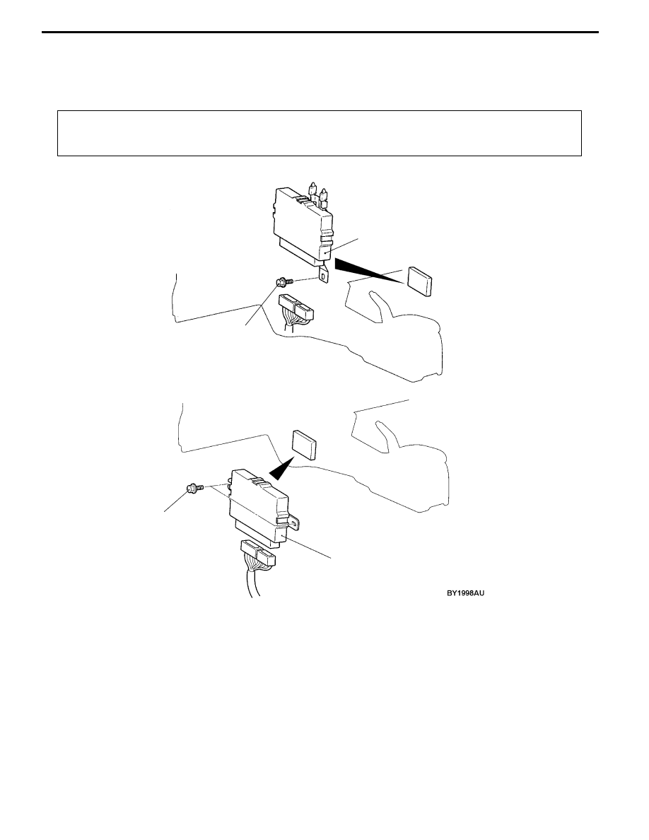
4WD-ECU <VEHICLES WITH ACD OR VEHICLES WITH ACD AND

AYC>

REMOVAL AND INSTALLATION

Pre-removal and Post-installation Operation
D

Cowl Side Trim <R.H.> Removal and Installation. (Refer to GROUP 52A - Trims.) <L.H. drive vehicles>

D

Front floor Console Removal and Installation. (Refer to GROUP 52A - Floor Console.) <R.H. drive vehicles>

4.9 ± 0.9 N m

4WD-ECU

4.9 ± 0.9 N m

4WD-ECU

<L.H. drive vehicles>

<R.H. drive vehicles>

MANUAL TRANSMISSION -

Sensor, Switch and Relay <Vehicles with ACD
or vehicles with ACD and AYC>

22A-56

SENSOR, SWITCH AND RELAY <VEHICLES WITH ACD OR

VEHICLES WITH ACD AND AYC>

REMOVAL AND INSTALLATION

Caution

Before removing the steering wheel and air bag module assembly, be sure to refer to GROUP

52B Precautions in Servicing and Airbag Module Clock Spring.

1

3

2

4

5

Parking brake lever

Steering wheel sensor removal

steps
D

Steering wheel and column cover

(Refer to GROUP 37A.)

1. Steering wheel sensor

G sensor removal steps

D

Floor console (Refer to GROUP 52A.)

2. Longitudinal G sensor

3. Lateral G sensor

Electric pump relay removal

4. Electric pump relay

ACD mode switch removal steps
D

Instrument panel ornament (Refer to

GROUP 52A – Instrument Panel.)

5. ACD mode switch

NOTE

For details on the wheel speed sensor, refer to GROUP

35B.

REMOVAL SERVICE POINT

A

ASTEERING WHEEL SENSOR REMOVAL

Remove the steering wheel sensor from the column switch.
Caution

Make sure no oil adheres to the steering wheel sensor

because a photocoupler is used.

Steering wheel sensor

MANUAL TRANSMISSION -

Sensor, Switch and Relay <Vehicles with ACD or

vehicles with ACD and AYC>

22A-57

INSPECTION

ELECTRIC PUMP RELAY CONTINUITY CHECK
1. Using a jumper wire, connect a battery (+) to terminal

13 of the electric pump relay and battery (-) to terminal

1.

2. While intermittently disconnecting the jumper wire at the

battery side, check for continuity between terminals 4

and 5 of the electric pump relay.

Jumper wire

Continuity between No.4 - No.5

Connected

Continuity

Disconnected

No continuity

ACD MODE SWITCH CONTINUITY CHECK

ACD mode switch

terminal

ACD mode switch

Continuity

No.1 - No.2

ON

Continuity

OFF

No continuity

No.3 - No.4

-

Continuity

NOTES


Content   ..  256  257  258  259   ..