Mitsubishi Lancer Evolution 7. Manual - part 256
MANUAL TRANSMISSION - Transmission Control
22A-47
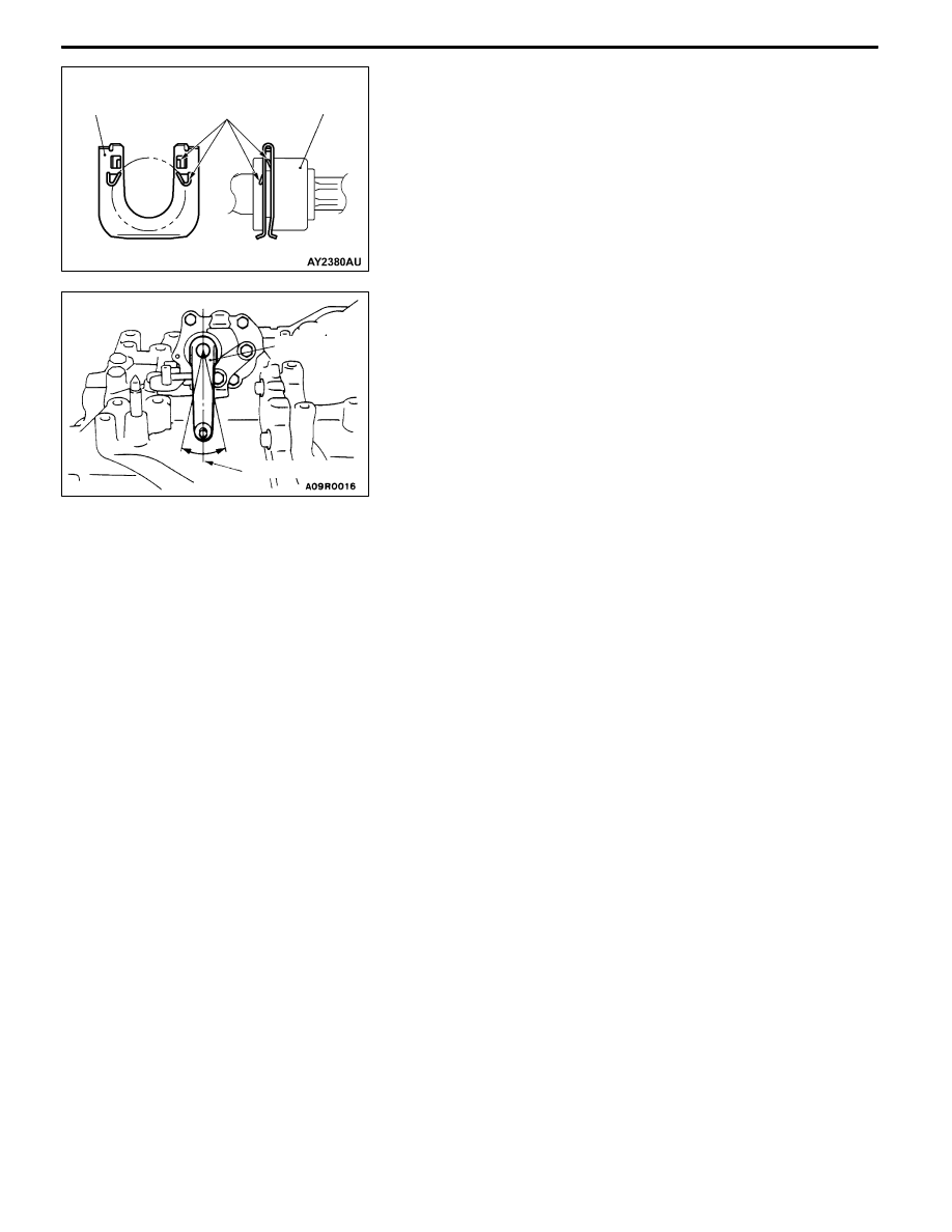
REMOVAL SERVICE POINT
A
A" CLIP/SELECT CABLE CONNECTION
(TRANSMISSION)/SHIFT CABLE (TRANSMISSION)
INSTALLATION
Push up the claws of the clip using a screwdriver, etc., and
then remove the clip from the bracket together with the cables.
INSTALLATION SERVICE POINT
"
AA CLIP/SELECT CABLE AND SHIFT CABLE
ASSEMBLY/SHIFT CABLE CONNECTION/SELECT
CABLE CONNECTION INSTALLATION
1. Set the transmission side shift lever and the passenger
compartment side shift lever to the neutral position.
2. Install the painted part of the shift cable end (transmission
side) and painted part of the select cable (transmission
side) facing the snap pin.
3. After installing the new clip to the cable bracket of the
transmission, install the shift cable and select cable to
the cable bracket.
4. Move the shift lever to all positions and check that the
operation is smooth.
Clip
Claws
Shift cable,
select cable
Neutral position
Select lever