Mitsubishi Lancer Evolution 7. Manual - part 226
ENGINE ELECTRICAL -
Charging System
16-3
ALTERNATOR SPECIFICATIONS
Items
Specifications
Type
Battery voltage sensing
Rated output V/A
12/90
Voltage regulator
Electronic built-in type
SERVICE SPECIFICATIONS
Items
Standard value
Limit
Alternator output line voltage drop (at 30 A) V
-
max. 0.3
Regulated voltage ambient
temp at voltage regulator V
- 20_C
14.2- 15.4
-
temp. at voltage regulator V
20_C
13.9-14.9
-
60_C
13.4- 14.6
-
80_C
13.1- 14.5
-
Output current
-
70 % of normal output current
Rotor coil resistance Ω
Approx. 3 - 5
-
Protrusion length of brush mm
-
2
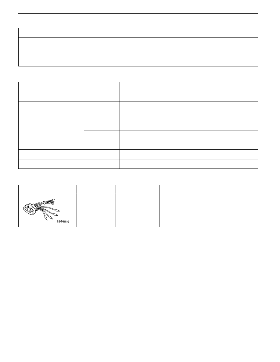
SPECIAL TOOL
Tool
Number
Name
Use
MB991519
Alternator test
harness
Checking the alternator (S terminal voltage)