Mitsubishi Lancer Evolution 7. Manual - part 177
MPI -
Special Tools
13A-7
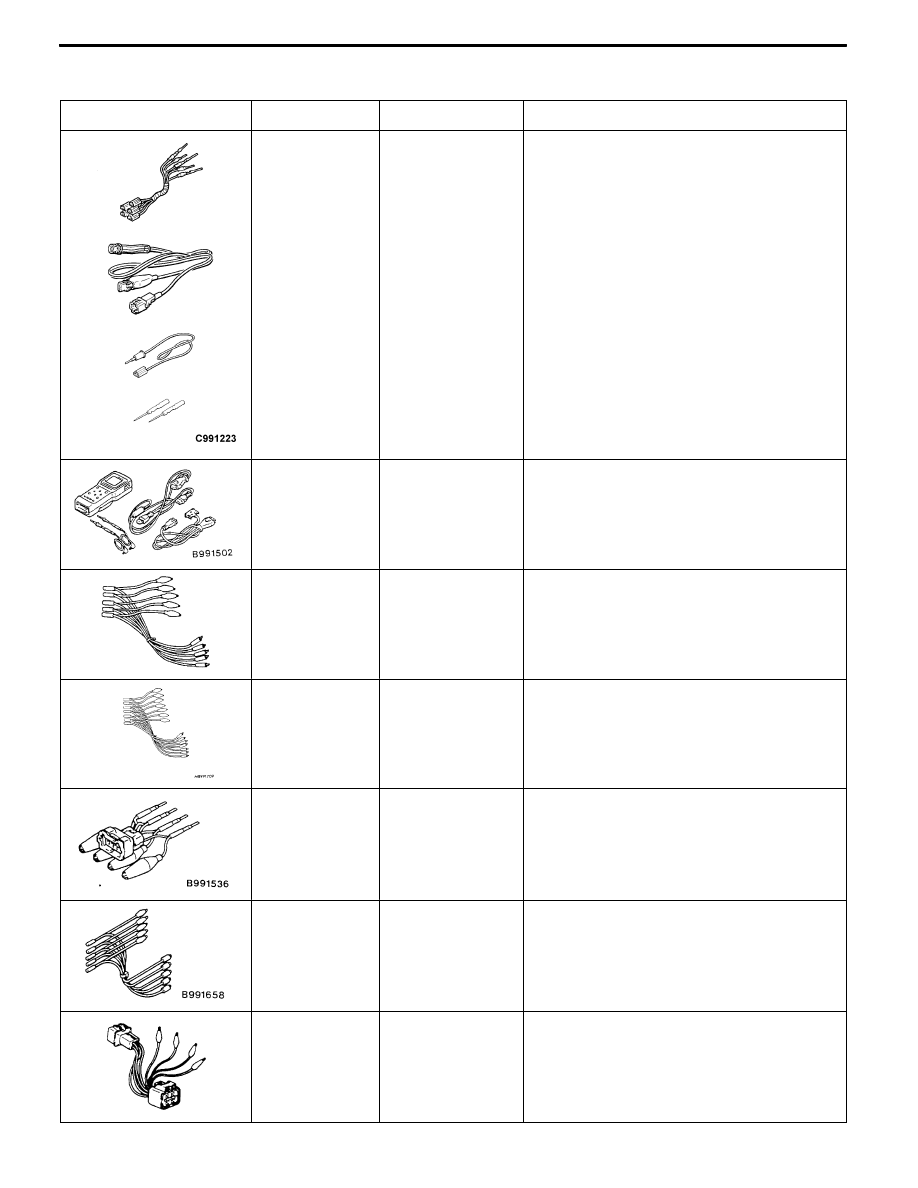
SPECIAL TOOLS
Tool
Number
Name
Use
B
A
C
D
MB991223
A: MB991219
B: MB991220
C: MB991221
D: MB991222
Harness set
A: Test harness
B: LED harness
C: LED harness
adapter
D: Probe
D
Check at the ECU terminals
A: Connector pin contact pressure inspection
B: Power circuit inspection
C: Power circuit inspection
D: Commercial tester connection
MB991502
MUT-II sub
assembly
D
Reading diagnosis code
D
MPI system inspection
MB991348
Test harness set
D
Inspection using an analyzer
MB991709
Test harness
D
Measurement of voltage during trouble-
shooting
D
Inspection using an analyzer
D
Idle speed control servo (stepper motor)
check
MB991536
Check harness for
TPS adjustment
D
Adjustment of throttle position sensor
D
Measurement of voltage during trouble-
shooting
MB991658
Test harness
D
Measurement of voltage during trouble-
shooting
D
Inspection using an analyzer
MD998464
Test harness
(4 pin, square)
D
Measurement of voltage during trouble-
shooting
D
Oxygen sensor (front) check