Mitsubishi Lancer Evolution 7. Manual - part 142


  Index      Mitsubishi     Mitsubishi Lancer Evolution 7 - service repair manual


Search            


Content   ..  140  141  142  143   ..


Mitsubishi Lancer Evolution 7. Manual - part 142


GENERAL -

Supplemental Restraint System (SRS)

00-21

SUPPLEMENTAL RESTRAINT SYSTEM (SRS)

To improve safety, the SRS and seat belts with

pre-tensioner. These systems enhance collision

safety by restraining the front passengers in case

of an accident. The SRS works with the

pre-tensioner simultaneously when a collision is

detected.

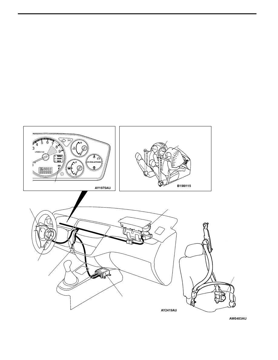
The SRS consists of two air bag modules, SRS

air bag control unit (SRS-ECU), SRS warning lamp

and clock spring. The air bags are located in the

center of the steering wheel, above the glove box.

Each air bag has a folded air bag and an inflator

unit. The SRS-ECU under the floor console monitors

the system and has a safing G-sensor and an

analog G-sensor. The warning lamp on the

instrument panel indicates the operational status

of the SRS. The clock spring is installed in the

steering column. The seat belt pre-tensioner is built

into the front seat belt retractor. Only authorized

service personnel should do work on or around

the SRS components and seat belt with

pre-tensioner. Those service personnel should read

this manual carefully before starting any such work.

Extreme care must be used when servicing the

SRS to avoid injury to the service personnel (by

inadvertent deployment of the air bags or

inadvertent operation of the seat belt with

pre-tensioner) or the driver (by rendering the SRS

or the seat belt with pre-tensioner inoperative).

Diagnosis

connector

Front passenger’s

air bag module

Clock spring

Driver’s air bag

module

SRS-ECU

SRS warning lamp

Driver’s air bag Front

passenger’s

air bag

Seat belt with

pre-tensioner

GENERAL -

Supplemental Restraint System (SRS)

00-22

SRS SERVICE PRECAUTIONS

1. In order to avoid injury to yourself or others

from accidental deployment of the air bag and

accidental operation of the seat belt with

pre-tensioner during servicing, read and

carefully follow all the precautions and

procedures described in this manual.

2. Do not use any electrical test equipment on

or near SRS components, except those

specified on P.52B-6.

3. Never Attempt to Repair the Following

Components:
D

SRS air bag control unit (SRS-ECU)

D

Clock spring

D

Driver’s and front passenger’s air bag

modules

D

Seat belt with pre-tensioner

NOTE

If any of these components are diagnosed as

faulty, they should only be replaced, in

accordance with the INDIVIDUAL COM-

PONENTS SERVICE procedures in this

manual. (Refer to P.52B-49.)

4. After disconnecting the negative (–) battery cable,

wait 60 seconds at least before any service and

insulate the disconnected cable with tape. The SRS

retain enough voltage to deploy the air bags for a

short time even after the disconnection of the battery.

So, serious injury may result by accidental air bag

deployment if a work is done on the SRS just after

the disconnection of the battery.

5. Do not attempt to repair the wiring harness connectors

of the SRS. If the connector(s) are diagnosed as defective,

replace the wiring harness(es). If the harness(es) are

diagnosed as faulty, replace or repair the wiring

harness(es) according to the table that follows.

Insulating tape

Battery

SRS-ECU connector

GENERAL -

Supplemental Restraint System (SRS)

00-23

SRS-ECU

Terminal No.

Destination of harness

Corrective action

7

Instrument panel wiring harness → Earth

Repair or replace each wiring

harness

8

Instrument panel wiring harness → Combination meter

(SRS warning lamp)

harness

9, 10

Instrument panel wiring harness → Front passenger’s air bag

module

11, 12

Instrument panel wiring harness → Clock spring → Driver’s air bag

module)

Repair or replace the dash wiring

harness. Replace clock spring.

13

Instrument panel wiring harness → Junction block (fuse No.3)

Repair or replace each wiring

harness

16

Instrument panel wiring harness → Junction block (fuse No.2)

harness.

20

Instrument panel wiring harness → Diagnosis connector

29, 30

Floor wiring harness → Driver’s seat belt pre-tensioner

27, 28

Floor wiring harness → Front passenger’s seat belt pre-tensioner

6. Inspection of the SRS-ECU harness connector should be carried out by the following procedure.

Insert the special tool (probe, MB991222, in the harness set) into the connector from harness side

(rear side), and connect the tester to this probe. If any tool than specified is used, damage to the

harness and other components will result. Furthermore, measurement should not be carried out by

touching the probe directly against the terminals from the front of the connector. The terminals are

plated to increase their conductivity, so that if they are touched directly by the probe, the plating

may break, which will cause drops in reliability.

MB991222

SRS-ECU harness connector

SRS-ECU harness connector (rear view)

7. SRS components and seat belt with pre-tensioner should not be subjected to hart, so remove the

SRS-ECU, driver’s and front passenger’s air bag modules, clock spring, and seat belt with pre-tensioner

before drying or baking the vehicle after painting.
D

SRS-ECU, air bag module, clock spring : 93℃ or more

D

Seat belt with pre-tensioner : 90℃ or more

8. Whenever you finish servicing the SRS, check warning lamp operation to make sure that the system

functions properly. (Refer to P.52B-6.)

9. Make certain that the ignition switch is LOCK (OFF) position when the MUT-II is connected or

disconnected.

10. If you have any questions about the SRS, please contact your local distributor.

NOTE

SERIOUS INJURY CAN RESULT FROM UNINTENDED AIR BAG DEPLOYMENT, SO USE ONLY

THE PROCEDURES AND EQUIPMENT SPECIFIED IN THIS MANUAL.

GENERAL -

Support Locations for Lifting and Jacking

00-24

SUPPORT LOCATIONS FOR LIFTING AND JACKING

Caution

Do not support the vehicles at locations other than specified supporting points. Doing so will

cause damage, etc.

SUPPORT POSITIONS FOR A GARAGE JACK AND AXLE STANDS

GARAGE JACK

Caution

Never support any point other than the specified ones, or deformation will result.


Content   ..  140  141  142  143   ..