Index Mitsubishi Mitsubishi Lancer Evolution 7 - service repair manual
Search
Content .. 82 83 84 85 ..
Mitsubishi Lancer Evolution 7. Manual - part 84
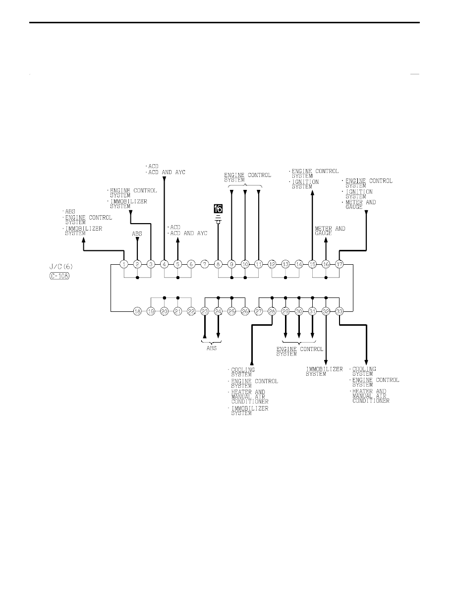
CIRCUIT DIAGRAMS
H1J00X09CB
B-67