Mitsubishi Lancer Evolution 7. Manual - part 51
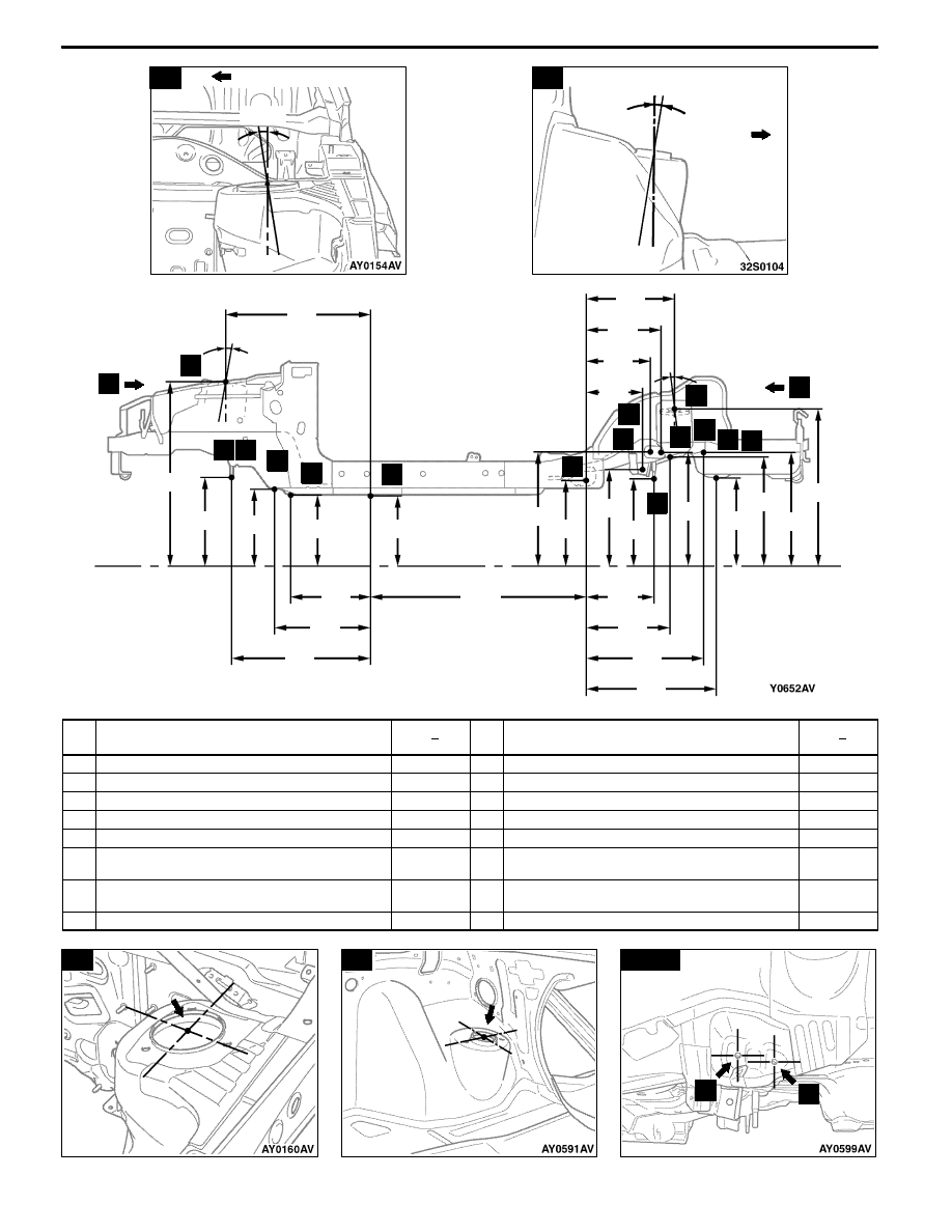
BODY DIMENSIONS -
Type A (Projected Dimensions)
A
Centre of vehicle
4°24′
B
Centre of
vehicle
11
°
36
′
12
13
1,21
21
19
B-7
104
1°
1,257
835
753
239
863
628
175
217
336
100
477
358
348
3°12′
A
563
401
523
162
330
345
707
B
3
4
12
13
14 15
16
17
18
19
20
21
22 23
529
440
191
339
199
716
10
mm
No. Standard measurement point
Hole
Size
shape mm
No. Standard measurement point
Hole
Size
shape mm
3
Centre of crossmember mounting hole
○
-18
17
Trailing arm mounting position
-
4
Centre of front fioor sidemember positioning hole
○
-25
18
Control link mounting position
-
10
Centre of crossmember mounting hole
○
-14
19
Centre of upper link mounting hole
○
-14
12
Centre of strut insulator
○
-110
20
Front edge of differential support mounting bolt
-
13
Centre of rear shock absorber mounting hole
○
-68
21
Centre of upper link mounting hole
○
-14
14
Front edge of crossmember mounting bolt (Left
side)
-
22
Centre of upper arm mounting hole
○
-13
15
Front edge of crossmember mounting bolt (Right
side)
-
23
Centre of crossmember mounting hole
○
-15
16
Centre of crossmember mounting hole
○
-11