Mitsubishi Lancer Evolution VI. Manual - part 95
SRS –
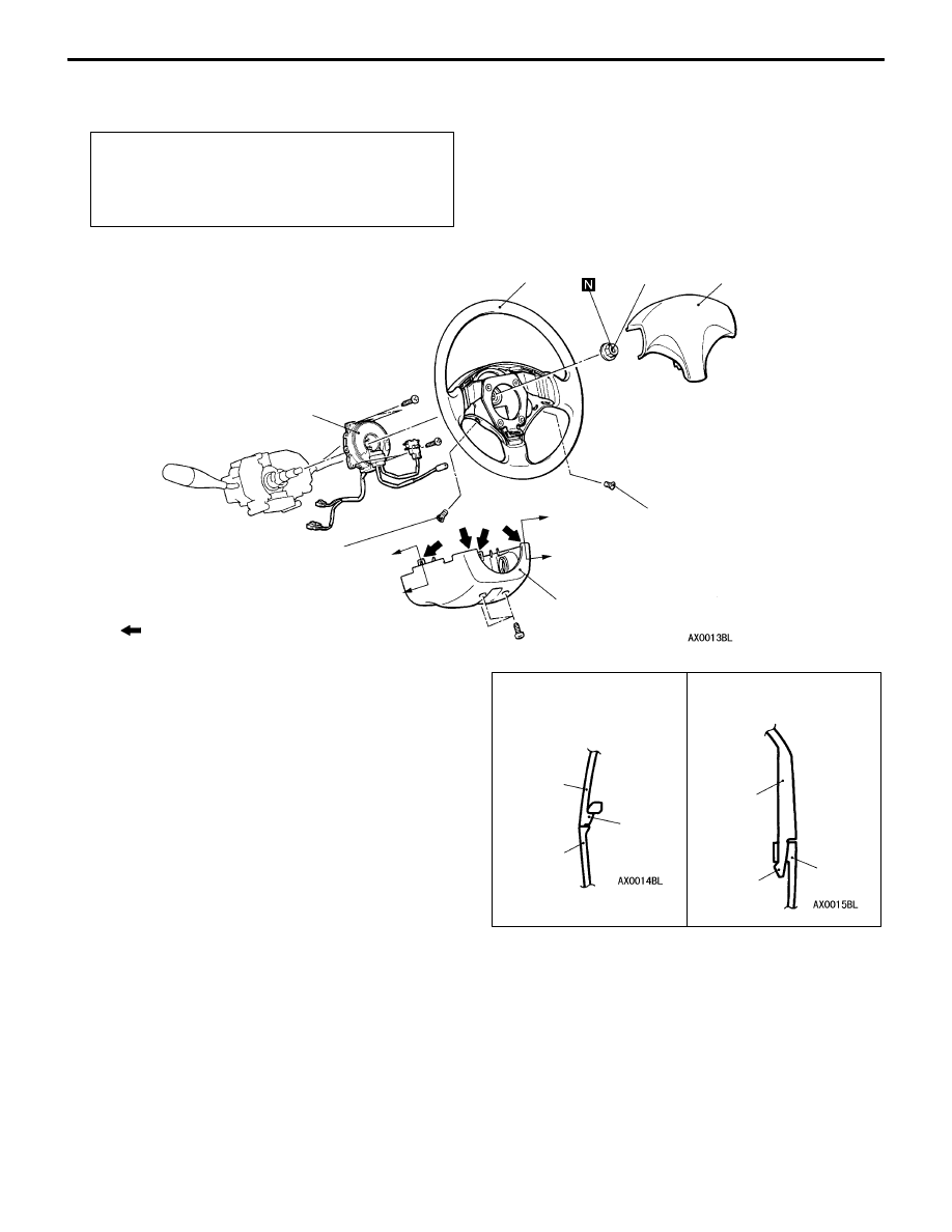
Air Bag Modules and Clock Spring
52B-26
REMOVAL AND INSTALLATION
<Air bag module (driver’s side), clock spring>
Pre-removal Operation
D
After setting the steering wheel and the front wheels
to the straight ahead position, remove the ignition
key.
D
Battery negative (–) terminal disconnection
41 Nm
2
3
4
1
A
B
8.9 Nm
NOTE
: Indicates claw position.
Upper
column
cover
Claw
Section B – B
4
A
B
8.9 Nm
Section A – A
4
Upper
column
cover
Claw
Driver’s side air bag module
removal steps
A
A
"
1. Driver’s side air bag module
Clock spring removal steps
A
A
"
1. Driver’s side air bag module
A
B
"
2. Steering wheel
3. Lower column cover
A
C
"
4. Clock spring
Driver’s side air bag module
installation steps
"
A
A D
Pre-installation inspection
1. Driver’s side air bag module
D
Negative (–) battery cable connection
"
D
A D
Post-installation inspection
Clock spring installation steps
"
A
A D
Pre-installation inspection
"
B
A
4. Clock spring
3. Lower column cover
"
C
A
2. Steering wheel
1. Driver’s side air bag module
D
Negative (–) battery cable connection
"
D
A D
Post-installation inspection