Mitsubishi Lancer Evolution VI. Manual - part 68


  Index      Mitsubishi     Mitsubishi Lancer Evolution VI - service repair manual


Search            


Content   ..  66  67  68  69   ..


Mitsubishi Lancer Evolution VI. Manual - part 68


ABS  – 

Troubleshooting

35B-22

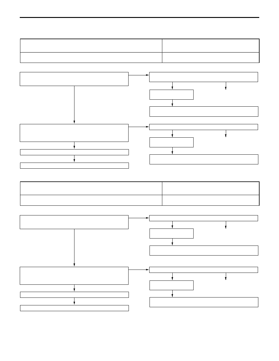
INSPECTION PROCEDURE FOR TROUBLE SYMPTOMS

Inspection Procedure 1 <EVOLUTION-IV>

Communication between the MUT-

II

 and the whole

system is not possible.

Probable cause

The cause may be a malfunction of the power supply circuit or the earth circuit of
the diagnosis connector.

D

Malfunction of diagnosis connector

D

Malfunction of wiring harness or connector

NG

Repair

NG

Replace the MUT-

II

.

NG

Repair

NG

Check the harness wire, and repair if necessary.

D

Between diagnosis connector and earth

OK

Check the trouble symp-
tom.

OK

Check the trouble symptom.

Measure at the diagnosis connector B-22.

D

Continuity between 4 and body earth, and between 5 and body
earth
OK: Continuity

NG

Check the following connectors: B-22, B-50

OK

NG

Check the harness wire, and repair if necessary.

D

Between power supply and diagnosis connector

OK

Check the trouble symp-
tom.

Measure at the diagnosis connector B-22.

D

Voltage between 16 and body earth
OK: System voltage

NG

Check the following connectors:
B-22, B-49, B-73, B-75

Inspection Procedure 1 <EVOLUTION-V, VI>

Communication between the MUT-

II

 and the whole

system is not possible.

Probable cause

The cause may be a malfunction of the power supply circuit or the earth circuit of
the diagnosis connector.

D

Malfunction of diagnosis connector

D

Malfunction of wiring harness or connector

NG

Repair

NG

Replace the MUT-

II

.

NG

Repair

NG

Check the harness wire, and repair if necessary.

D

Between diagnosis connector and earth

OK

Check the trouble symp-
tom.

OK

Check the trouble symptom.

Measure at the diagnosis connector B-22.

D

Continuity between 4 and body earth, and between 5 and body
earth
OK: Continuity

NG

Check the following connectors: B-22, B-50

OK

NG

Check the harness wire, and repair if necessary.

D

Between power supply and diagnosis connector

OK

Check the trouble symp-
tom.

Measure at the diagnosis connector B-22.

D

Voltage between 16 and body earth
OK: System voltage

NG

Check the following connectors: B-22, B-80

ABS  – 

Troubleshooting

35B-23

Inspection Procedure 2 <EVOLUTION-IV>

Communication between MUT-

II

 and the ABS-ECU is not

possible.

Probable cause

The cause may be an open circuit in the ABS-ECU power supply circuit or an open
circuit in the diagnosis output circuit.

D

Blown fuse

D

Malfunction of wiring harness or connector

D

Malfunction of ABS-ECU

NG

Repair

NG

Check the harness wire, and repair if necessary.

D

Between ABS-ECU and diagnosis connector

OK

NG

Repair

NG

Check the harness wire, and repair if necessary.

D

Between ignition switch and ABS-ECU

OK

NG

Repair

NG

Check the harness wire, and repair if necessary.

D

Between ABS-ECU and earth

NG

Repair

NG

Replace the ABS-ECU.

OK

Check the trouble symp-
tom.

OK

Check the trouble symp-
tom.

OK

Check the following connectors: B-24, B-25

Measure at the ABS-ECU connector terminals B-24 and B-25.

D

Disconnect the connector, and measure at the harness side
connector.

D

Continuity between 2 and body earth, between 31 and body
earth and between 39 and body earth
OK: Continuity

NG

Check the following connectors: B-24, B-25

OK

Check the trouble symp-
tom.

Measure at the ABS-ECU connector B-24.

D

Disconnect the connector, and measure at the harness side
connector.

D

Ignition switch: ON

D

Voltage between 26 and body earth
OK: System voltage

NG

Check the following connectors:
B-24, B-52, B-74, B-76

OK

Check the trouble symp-
tom.

Measure at the diagnosis connector B-22 and the ABS-ECU connec-
tor B-25.

D

Disconnect the connector, and measure at the harness side
connector.

D

Continuity between the following terminals
ABS-ECU side – Diagnosis connector side

33  –  1
41  –  7

OK: Continuity

NG

Check the following connectors:
B-22, B-25, B-32, B-65

ABS  – 

Troubleshooting

35B-24

Inspection Procedure 2 <EVOLUTION-V, VI>

Communication between MUT-

II

 and the ABS-ECU is not

possible.

Probable cause

The cause may be an open circuit in the ABS-ECU power supply circuit or an open
circuit in the diagnosis output circuit.

D

Blown fuse

D

Malfunction of wiring harness or connector

D

Malfunction of ABS-ECU

NG

Repair

NG

Check the harness wire, and repair if necessary.

D

Between ABS-ECU and diagnosis connector

OK

NG

Repair

NG

Check the harness wire, and repair if necessary.

D

Between ignition switch and ABS-ECU

OK

NG

Repair

NG

Check the harness wire, and repair if necessary.

D

Between ABS-ECU and earth

NG

Repair

NG

Replace the ABS-ECU.

OK

Check the trouble symp-
tom.

OK

Check the trouble symp-
tom.

OK

Check the following connectors: B-24, B-25

Measure at the ABS-ECU connector terminals B-24 and B-25.

D

Disconnect the connector, and measure at the harness side
connector.

D

Continuity between 15 and body earth, between 25 and body
earth and between 42 and body earth
OK: Continuity

NG

Check the following connectors: B-24, B-25

OK

Check the trouble symp-
tom.

Measure at the ABS-ECU connector B-24.

D

Disconnect the connector, and measure at the harness side
connector.

D

Ignition switch: ON

D

Voltage between 13 and body earth
OK: System voltage

NG

Check the following connectors:
B-24, B-52, B-74, B-76

OK

Check the trouble symp-
tom.

Measure at the diagnosis connector B-22 and the ABS-ECU connec-
tor B-25.

D

Disconnect the connector, and measure at the harness side
connector.

D

Continuity between the following terminals
ABS-ECU side – Diagnosis connector side

47  –  1
36  –  7

OK: Continuity

NG

Check the following connectors:
B-22, B-25, B-32, B-65

ABS  – 

Troubleshooting

35B-25

Inspection Procedure 3

When the ignition key is turned to “ON” (engine stopped),
the ABS warning lamp does not illuminate.

Probable cause

The ABS-ECU turns the valve relay ON 

 OFF 

 ON for initial checking when

it is powered ON. Accordingly, the ABS warning lamp illuminates twice even if the
circuit between the ABS warning lamp and ABS-ECU is faulty.
The cause may be an open circuit in the lamp power supply circuit, a blown lamp,
an open circuit between the ABS warning lamp and ABS-ECU or between the ABS
warning lamp and the valve relay.

D

Blown fuse

D

Burn out ABS warning lamp bulb

D

Malfunction of wiring harness or connector

OK

Check the trouble symptom.

NG

Replace the combination meter.

OK

Check the following connectors:
B-08, B-09

NG

Repair

OK

Check the trouble symptom.

NG

Check the harness wire, and repair
if necessary.

D

Between ignition switch and ABS
warning lamp

OK

Check the trouble symptom.

NG

Check the harness wire, and repair
if necessary.

D

Between ABS warning lamp and
ABS-ECU

D

Between ABS warning lamp and
valve relay

OK

Check the following connectors:
A-76, B-09, B-52

NG

Repair

OK

Measure at the combination meter con-
nector B-09.

D

Disconnect the connector, and
measure at the combination meter
side connector.

D

Ignition switch: ON

D

ABS warning lamp condition when
terminal 12 is grounded.
OK: Illuminates

NG

Check whether the ABS warning lamp
bulb is burnt out.

NG

OK

Measure at the combination meter con-
nector B-08.

D

Disconnect the connector and
measure at the harness side
connector.

D

Ignition switch: ON

D

Voltage between 42 and body
ground
OK: System voltage

NG

Check the following connectors:
B-08, B-75, B-76

NG

Repair

Fuse check
General-purpose fuse No.4

NG

Refer to GROUP 00 – Inspection Ser-
vice Points for a Blown Fuse.

Replace the ABS warning lamp bulb.


Content   ..  66  67  68  69   ..