Mitsubishi Lancer Evolution VI. Manual - part 67
ABS –
Troubleshooting
35B-18
<EVOLUTION-IV>
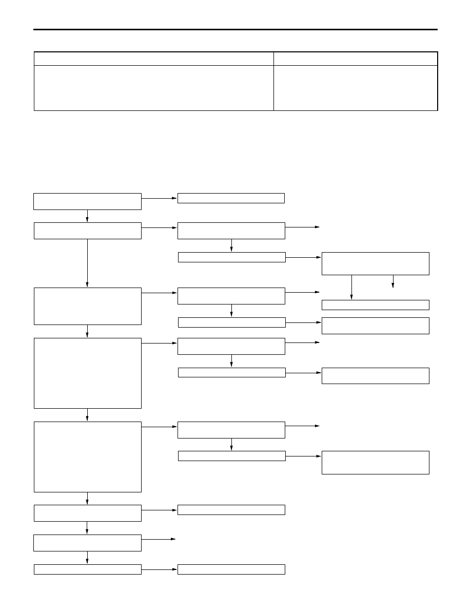
Code No.53 Motor relay system
Probable cause
This code is output under any of the following conditions:
D
No signals are input to the motor monitor when the motor relay is ON (motor
does not run, etc.).
D
A signal is being input to the motor monitor for 3 sec. or more when the motor
relay is OFF (motor continues running, etc.).
D
The motor relay is inoperative.
D
Defective motor relay
D
Defective harness or connector
D
Defective hydraulic unit
D
Defective ABS-ECU
Caution
(1) If the motor relay contacts fuse, the motor continues running even when the ignition switch
is turned OFF. In this case, immediately remove fusible link No. 8 (60 A) or disconnect the
A-22 hydraulic unit connector or A-77 motor relay connector. Overloading the motor results
in a rundown battery.
(2) Driving the motor through actuator test runs down the battery. After the test, run the engine
for some while.
OK
Check the trouble symptom.
NG
Check and repair the harness between
fusible link No. 8 and motor relay.
OK
Check the trouble symptom.
NG
Check and repair the harness between
motor relay and hydraulic unit.
OK
Check the trouble symptom.
NG
Check and repair the harness between
motor relay and ABS-ECU motor
monitor terminal No. 35.
OK
Check the trouble symptom.
NG
Replace ABS-ECU.
OK
Check the following connectors:
A-22, A-77, B-25
NG
Repair
OK
Check the motor for operation.
(Refer to P.35B-43.)
NG
Replace the hydraulic unit.
OK
Measure at A-77 motor relay connector
and B-25 ABS-ECU connector.
D
Disconnect the connector and
measure at the harness side.
D
Continuity across the following
terminals
Motor relay
ABS-ECU
side
side
4
–
35
OK: Conducting
NG
Check the following connectors:
A-77, B-25
NG
Repair
OK
Measure at A-77 motor relay connector
and A-22 hydraulic unit connector.
D
Disconnect the connector and
measure at the harness side.
D
Continuity across the following
terminals
Motor relay
Hydraulic
side
unit side
4
–
12
OK: Conducting
NG
Check the following connectors:
A-22, A-77
NG
Repair
NO
Measure at A-77 motor relay connector.
D
Disconnect the connector and
measure at the harness side.
D
Voltage across 5 and body ground
OK: System voltage
NG
Check the following connector:
A-77
NG
Repair
OK
Replace ABS-ECU.
Repair
NG
OK
Check the trouble symptom.
NG
Check the harness between motor
relay and ABS-ECU motor monitor
terminal No. 35.
OK
MUT-
II
Actuator test
Motor operating sounds heard?
YES
Check the following connector:
B-25
NG
Repair
Check the motor relay.
(Refer to P.35B-39.)
NG
Replace the motor relay.