Mitsubishi Lancer Evolution VI. Manual - part 48


  Index      Mitsubishi     Mitsubishi Lancer Evolution VI - service repair manual


Search            


Content   ..  46  47  48  49   ..


Mitsubishi Lancer Evolution VI. Manual - part 48


CLUTCH OVERHAUL – 

Clutch Release Cylinder

21B-10

REASSEMBLY SERVICE POINT

"

A

A

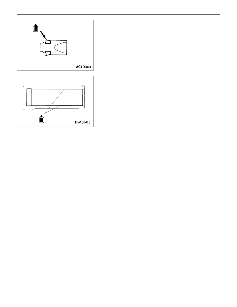
PISTON / PISTON CUP INSTALLATION

After applying brake fluid to the inside wall surface of the
release cylinder and all the circumferential surfaces of the
piston and piston cup, insert the piston and piston cup into
the cylinder.

Specified brake fluid:

Brake fluid SAE J1703 (DOT3)

INSPECTION

RELEASE CYLINDER

Check the inside wall surface of the release cylinder for rust
and damage.
Using a cylinder gauge, measure the inside diameter of the
release cylinder at about three positions (the deepest, middle
and brim positions).  If the clearance from the outside diameter
of the piston exceeds the limit, replace the release cylinder
as an assembly.

Limit: 0.15 mm

CLUTCH – 

General / Service Specifications / 
Lubricants / On-vehicle Service

21A-2

GENERAL

OUTLINE OF CHANGE

D

The service procedures for left-hand drive vehicles have been established as described below.

SERVICE SPECIFICATIONS <L.H. DRIVE VEHICLES>

Items

Standard value

Clutch pedal height  mm

163.5–166.5

Clutch pedal clevis pin play  mm

1–3

Clutch pedal free play   mm

6–13

Distance between the clutch pedal and the toeboard when
the clutch is disengaged  mm

85 or more

LUBRICANTS <L.H. DRIVE VEHICLES>

Items

Specified lubricants

Quantity

Clutch fluid

Brake fluid DOT 3 or DOT 4

As required

Push rod assembly

Rubber grease

Boot

Release cylinder push rod

MITSUBISHI genuine grease
Part No. 0101011

ON-VEHICLE SERVICE 
<L.H. DRIVE VEHICLES>

CLUTCH PEDAL INSPECTION AND
ADJUSTMENT

1.

Turn up the carpet, etc. under the clutch pedal.

2.

Measure the clutch pedal height.
Standard value (A): 163.5 – 166.5 mm

3.

If the height of the clutch pedal is outside the standard
value, loosen the locking nut and adjust the pedal height
to the standard value using the adjusting bolt or push
rod.

Clutch pedal height

A

Setting nut

Adjusting bolt

Locking
nut

13 Nm

CLUTCH  – 

On-vehicle Service

21A-3

4.

Measure the clutch pedal play.

Standard value (B): 1 – 3 mm

5.

If the clutch pedal play is not within the standard value,
loosen the setting nut and move the push rod to adjust.

Caution
Do not push in the master cylinder push rod at this
time.

6.

After completing the adjustments, confirm that the clutch
pedal free play (measured at the face of the pedal pad)
and the distance between the clutch pedal (the face of
the pedal pad) and the toeboard when the clutch is
disengaged are within the standard value ranges.

Standard value (C): 6– 13 mm
Standard value (D): 85 mm or more

7.

If the clutch pedal free play and the distance between
the clutch pedal and the toeboard when the clutch is
disengaged do not agree with the standard values, it
is probably the result of either air in the hydraulic system
or a faulty master cylinder or clutch. Bleed the air, or
disassembly and inspect the master cylinder or clutch.

8.

Turn back the carpet, etc.

BLEEDING

Specified fluid: Brake fluid DOT 3 or DOT 4

Caution
Use the specified brake fluid. Avoid using a mixture of
the specified fluid and other fluid.

Clutch pedal clevis pin play

B

Clutch pedal free play

Distance between the clutch pedal and the
toeboard when the clutch is disengaged

C

D


Content   ..  46  47  48  49   ..