Mitsubishi Eclipse / Eclipse Spyder (2000-2002). Service and repair manual - part 590


  Index      Mitsubishi     Mitsubishi Eclipse / Eclipse Spyder (2000-2002). Service and repair manual


Search            


Content   ..  588  589  590  591   ..


Mitsubishi Eclipse / Eclipse Spyder (2000-2002). Service and repair manual - part 590


HYDRAULIC UNIT

TSB Revision

ANTI-LOCK BRAKING SYSTEM (ABS)

35B-51

H YD R A U LIC  U N IT

REMOVAL AND INSTALLATION

M1352008600066

NOTE: The ABS-ECU is integrated in the hydraulic unit.

REMOVAL SERVICE POINTS

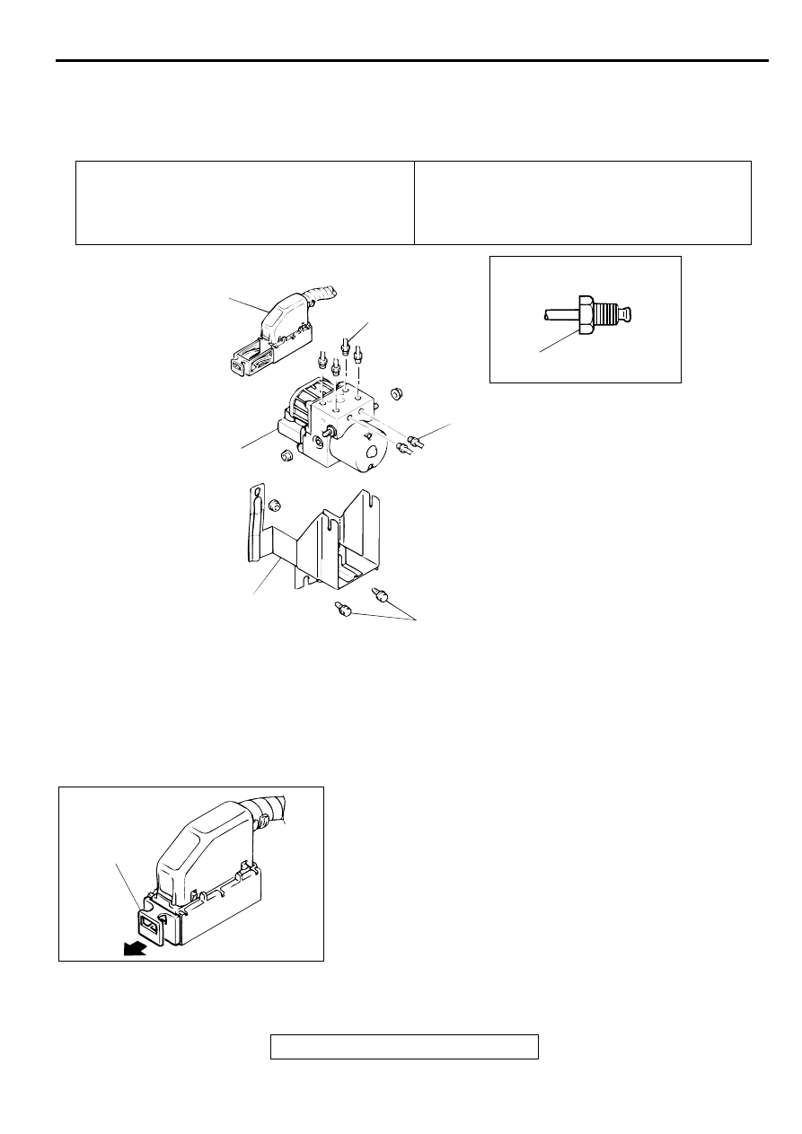
<<A>> HARNESS CONNECTOR REMOVAL
Pull the lock lever in the direction shown in the illustration, and 
remove the harness.

Pre-removal Operation

Strut Tower Bar Removal <Vehicles with Strut Tower Bar> 
(Refer to GROUP 42, Strut Tower Bar 

P.42-11

.)

Brake Fluid Draining

Post-installation Operation

Brake Fluid Filling

Bake Line Bleeding (Refer to 

P.35B-45

.)

Strut Tower Bar Installation <Vehicles with Strut Tower 
Bar> (Refer to GROUP 42, Strut Tower Bar 

P.42-11

.)

AC000956 AB

15 ± 2 N·m
11 ± 1 ft-lb

30 ± 5 N·m
22 ± 4 ft-lb

2

1

1

4

3

REMOVAL STEPS

>>A<<

1. BRAKE TUBE

<<A>>

2. HARNESS CONNECTOR

3. BRACKET ASSEMBLY

<<B>>

4. HYDRAULIC UNIT

REMOVAL STEPS (Continued)

AC000957 AB

LOCK LEVER

HYDRAULIC UNIT

TSB Revision

ANTI-LOCK BRAKING SYSTEM (ABS)

35B-52

<<B>> HYDRAULIC UNIT REMOVAL

WARNING

The hydraulic unit is heavy. Use care when removing 
it.

CAUTION

The hydraulic unit cannot be disassembled. Never 
loosen its nuts or bolts.

Do not drop or shock the hydraulic unit.

Do not turn the hydraulic unit upside down or lay it on 
its side.

INSTALLATION SERVICE POINT

>>A<< BRAKE TUBE INSTALLATION
Connect the tubes to the hydraulic unit as shown in the 
illustration.
1. To the proportioning valve (rear brake: LH)

2. To the proportioning valve (rear brake: RH)

3. From the master cylinder (primary)

4. From the master cylinder (secondary)

5. To the front brake (RH)

6. To the front brake (LH)

AC000958

5

4

1

6

3

2

AB

WHEEL SPEED SENSOR

TSB Revision

ANTI-LOCK BRAKING SYSTEM (ABS)

35B-53

WH EEL SPEED  SEN SO R

REMOVAL AND INSTALLATION

M1352008300087

REMOVAL SERVICE POINT

<<A>> FRONT SPEED SENSOR/REAR SPEED SENSOR 
REMOVAL

CAUTION

Be careful when handling the projection at the tip of the 
speed sensor and the toothed edge of the ABS rotor so as 
not to damage them by contacting other parts.

Post-installation Operation

Wheel Speed Sensor Output Voltage Measurement 
(Refer to 

P.35B-45

.)

AC000959 AB

<FRONT>

1

<REAR>

3

2

4

<<A>>

>>A<< 1. FRONT SPEED SENSOR

2. FRONT ABS ROTOR WITH 

DRIVESHAFT (REFER TO GROUP 
26, DRIVESHAFT 

P.26-11

.)

<<A>> >>A<<

3. REAR SPEED SENSOR
4. REAR ABS ROTOR (REFER TO 

GROUP 27, REAR AXLE HUB 

P.27-

5

.)

AC000960

PROJECTION

AB

WHEEL SPEED SENSOR

TSB Revision

ANTI-LOCK BRAKING SYSTEM (ABS)

35B-54

INSTALLATION SERVICE POINT

>>A<< FRONT SPEED SENSOR/REAR SPEED SENSOR 
INSTALLATION
The clearance between the wheel speed sensor and the ABS 
rotor's toothed surface is not adjustable, but measure the 
distance between the sensor installation surface and the ABS 
rotor's toothed surface.

Standard value: 28.2 

 28.5 mm (1.11 

 1.12 inches)

INSPECTION

M1352008400084

SPEED SENSOR CHECK

1. Check whether any metallic foreign material has adhered to 

the projection at the speed sensor tip. Remove any foreign 
material. Also check whether the pole piece is damaged. 
Replace it with a new one if it is damaged.

NOTE: The projection can become magnetized due to the 
magnet inside the speed sensor, causing foreign material to 
easily adhere to it. The projection may not be able to 
correctly sense the wheel rotation speed if foreign matter is 
on it or if it is damaged.

2. Measure the resistance between the speed sensor 

terminals.

Standard value: 1.28 

 1.92 k

3. If the internal resistance of the speed sensor is not within the 

standard value, replace it with a new speed sensor.

4. Remove all connections from the speed sensor. The circuit 

should be open between terminals (1) and (2) and the body 
of the speed sensor. If the circuit is not open, replace with a 
new speed sensor.

5. Check the speed sensor cable for breakage, damage or 

disconnection. Replace with a new one if a problem is found.

NOTE: When checking for cable damage, remove the cable 
clamp part from the body and then gently bend and pull the 
cable near the clamp.

AC000961

FRONT

REAR

AB

ABS
ROTOR'S
TOOTHED
SURFACE

ABS
ROTOR'S
TOOTHED
SURFACE

AC000960

PROJECTION

AB

AC000963

<FRONT,
  REAR LEFT>

<REAR RIGHT>

AB

AC000964

<FRONT,
  REAR LEFT>

<REAR RIGHT>

AB


Content   ..  588  589  590  591   ..