Mitsubishi Eclipse / Eclipse Spyder (2000-2002). Service and repair manual - part 560


  Index      Mitsubishi     Mitsubishi Eclipse / Eclipse Spyder (2000-2002). Service and repair manual


Search            


Content   ..  558  559  560  561   ..


Mitsubishi Eclipse / Eclipse Spyder (2000-2002). Service and repair manual - part 560


TRAILING ARM ASSEMBLY

TSB Revision

REAR SUSPENSION

34-13

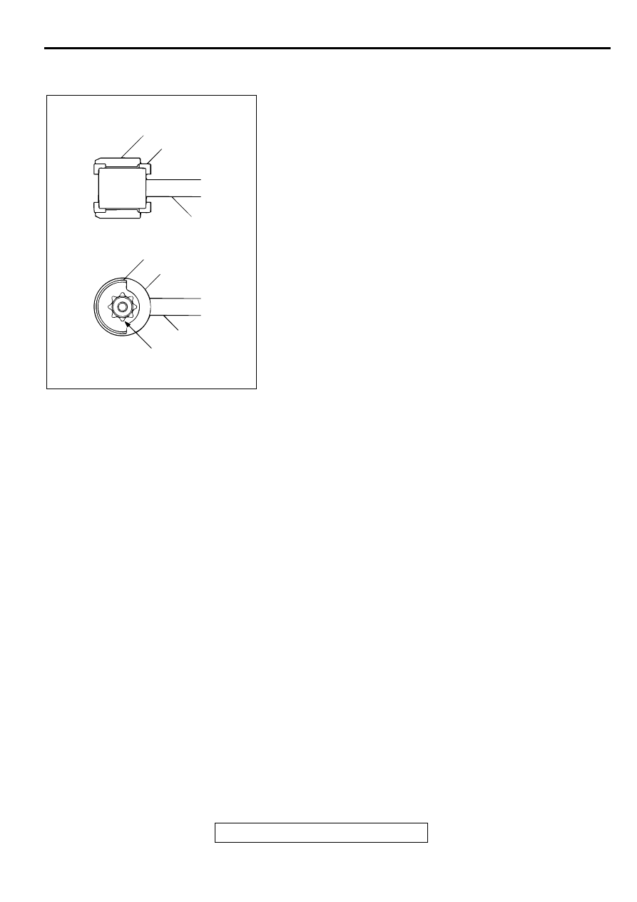
INSTALLATION SERVICE POINT

>>A<< STOPPER B/STOPPER A INSTALLATION
1. Install stopper B in the shown direction.

2. Install stopper A in the shown direction while checking that 

the notches on stopper A are engaged with the projections 
on the trailing arm bushing.

INSPECTION

M1341002300030

Check the bushings for wear and deterioration.

Check the trailing arm for bends or damage.

AC001059

STOPPER A

STOPPER A

STOPPER B

STOPPER B

TRAILING ARM

TRAILING ARM

NOTCHES AND PROJECTIONS

AB

LOWER ARM AND TOE CONTROL ARM ASSEMBLY

TSB Revision

REAR SUSPENSION

34-14

LO W ER AR M  AN D  TO E CO N TR O L A R M  ASSEM B LY

REMOVAL AND INSTALLATION

M1341004500063

CAUTION


*

: Indicates parts which should be temporarily tightened, and then fully tightened with the vehicle on 

the ground in the unladen condition.

Required Special Tools:

MB990326: Preload Socket

MB990635 or MB991113: Steering Linkage Puller

MB990800: Ball Joint Remover and Installer

Post-installation Operation

Check the Dust Cover for Cracks or Damage by Pushing 
it with Your Finger. 

Wheel Alignment Check and Adjustment (Refer to 

P.34-

5

.)

AC001064

8

8

N

6

2

1

3

N

4

7

5

AD

108 ± 10 N·m*
80 ± 7 ft-lb*

29 ± 4 N·m
21 ± 3 ft-lb

74 ± 4 N·m*
55 ± 3 ft-lb*

39 ± 5 N·m
29 ± 4 ft-lb

98 ± 10 N·m*
73 ± 7 ft-lb*

LOWER ARM ASSEMBLY 
REMOVAL STEPS

1.

STABILIZER LINK CONNECTION

2.

WHEEL SPEED SENSOR 
MOUNTING BOLTS

3.

LOWER ARM ASSEMBLY AND 
KNUCKLE CONNECTING BOLT

4.

LOWER ARM ASSEMBLY 
MOUNTING BOLT

5.

LOWER ARM ASSEMBLY

TOE CONTROL ARM ASSEMBLY 
REMOVAL STEPS

<<A>>

6.

TOE CONTROL ARM AND 
KNUCKLE CONNECTION

<<B>>

7.

TOE CONTROL ARM ASSEMBLY 
MOUNTING BOLT

8.

TOE CONTROL ARM ASSEMBLY

LOWER ARM AND TOE CONTROL ARM ASSEMBLY

TSB Revision

REAR SUSPENSION

34-15

REMOVAL SERVICE POINTS

<<A>> TOE CONTROL ARM AND KNUCKLE 
DISCONNECTION

CAUTION

Use special tool MB990635 or MB991113 to loosen the 
nut only; do not remove it from the ball joint.

Tie special tool MB990635 or MB991113 with a cord to 
prevent it from falling off.

Use special tool MB990635 or MB991113 to disconnect the toe 
control arm and knuckle.

<<B>> TOE CONTROL ARM ASSEMBLY MOUNTING BOLT 
REMOVAL
Place mating marks on the crossmember and the plate before 
removing the bolt.

INSPECTION

M1341004600060

Check the bushings for wear and deterioration.

Check the lower arm or toe control arm for bends or 
damage.

Check all bolts for condition and straightness.

TOE CONTROL ARM BALL JOINT BREAKAWAY TORQUE 
CHECK
1. After shaking the ball joint stud several times, in order to 

make the ball joint turn smoothly, install the nut to the stud 
and use the special tool MB990326 to measure the 
breakaway torque of the ball joint.

Standard value: 1.0 

 3.1 N

m (8.9 

 27 in-lb)

2. When the measured value exceeds the standard value, 

replace the toe control arm assembly.

3. When the measured value is lower than the standard value, 

check that the ball joint turns smoothly without excessive 
play. If so, it is possible to re-use that ball joint.

ACX00715AC

BALL JOINT

CORD

NUT

MB991113 OR
MB990635

AC001065AB

PLATE

MATING MARKS

AC001091

MB990326

AC

LOWER ARM AND TOE CONTROL ARM ASSEMBLY

TSB Revision

REAR SUSPENSION

34-16

TOE CONTROL ARM BALL JOINT DUST COVER CHECK
1. Check the dust cover for cracks or damage by pushing it 

with your finger.

2. If the dust cover is cracked or damaged, replace the toe 

control arm assembly.

NOTE: Cracks or damage of the dust cover may cause 
damage to the ball joint. When it is damaged during service 
work, replace the dust cover.

TOE CONTROL ARM BALL JOINT DUST COVER 
REPLACEMENT

M1341014800043

If the dust cover is damaged accidentally during service work, 
replace the dust cover as follows:
1. Remove the dust cover.

2. Apply multipurpose grease to inside and lip of the dust 

cover.

3. Using special tool MB990800 press the dust cover until it 

contacts the snap ring.

4. Check the dust cover for cracks or damage by pushing it 

with your finger.

AC001066

MB990800

DUST COVER

SNAP RING

AB


Content   ..  558  559  560  561   ..