Mitsubishi Eclipse / Eclipse Spyder (2000-2002). Service and repair manual - part 553


  Index      Mitsubishi     Mitsubishi Eclipse / Eclipse Spyder (2000-2002). Service and repair manual


Search            


Content   ..  551  552  553  554   ..


Mitsubishi Eclipse / Eclipse Spyder (2000-2002). Service and repair manual - part 553


SPECIAL TOOLS

TSB Revision

FRONT SUSPENSION

33A-5

INSPECTION PROCEDURE 5: Noise

DIAGNOSIS

STEP 1. Check for lack of lubrication.

Q: Is lubrication inadequate?

YES : 

Lubricate it, then go to Step 5.

NO : 

Go to Step 2.

STEP 2. Check the tightened parts for looseness 
as well as the bushings for wear.

Q: Are the tightened parts and bushings in good 

condition?
YES : 

Go to Step 3.

NO : 

Replace it, then go to Step 5.

STEP 3. Check for broken coil spring.

Q: Is the coil spring broken?

YES : 

Replace it, then go to Step 5.

NO : 

Go to Step 4.

STEP 4. Check for strut assembly damage.

Q: Is the strut assembly damaged?

YES : 

Replace it, then go to Step 5.

NO : 

Go to Step 5.

STEP 5. Check symptoms.

Q: Is the malfunction eliminated?

YES : 

Return to Step 1.

NO : 

This diagnosis complete.
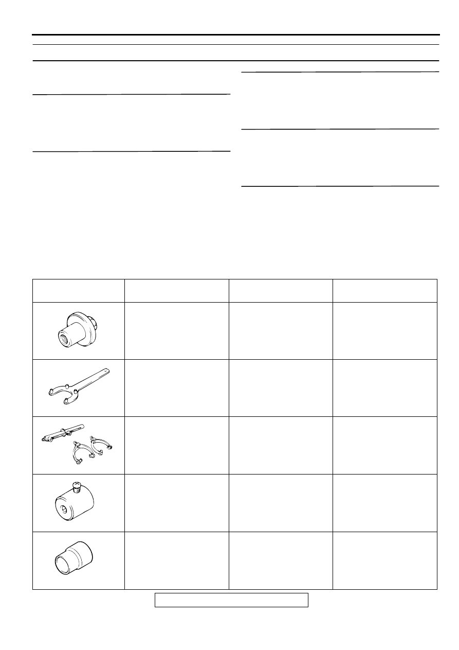
SPECIA L TO O LS

M1332000600060

TOOL

TOOL NUMBER AND 
NAME

SUPERSESSION

APPLICATION

MB991004
Wheel alignment gauge 
attachment

MB991004-01 or General 
service tool

Wheel alignment 
measurement

MB991176
Spring seat holder

General service tool

Strut disassembly and 
assembly

A: MB991237
Spring compressor 
body

B: MB991238
Arm set

MIT221369

Front coil spring 
compression

MB991006
Preload socket

MB990228-01

Lower arm ball joint 
breakaway torque check

MB990799
Ball joint dust cover 
installer

MB990799-01

Lower arm ball joint dust 
cover installation

MB991004

MB991176

MB991237

A

B

MB991006

MB990799

ON-VEHICLE SERVICE

TSB Revision

FRONT SUSPENSION

33A-6

O N -VEH IC LE SERVIC E

FRONT WHEEL ALIGNMENT CHECK AND 
ADJUSTMENT

M1331000900080

Required Special Tool:

MB991004: Wheel Alignment Gauge Attachment.

Measure wheel alignment with alignment equipment on a level 
surface. The front suspension, steering system, and wheels 
should be serviced to normal condition before measuring wheel 
alignment.
TOE-IN

Standard value: 0 

±

 3 mm (0 

±

 0.12 inch)

NOTE: If the toe-in is not within the standard value, adjust the 
toe-in by undoing the clips and turning the left and right tie rod 
turnbuckles by the same amount (in opposite directions).

NOTE: The toe will move out as the left turnbuckle is turned 
toward the front of the vehicle and the right turnbuckle is turned 
toward the rear of the vehicle.
For each one turn of the left and right tie rods, the toe-in will be 
adjusted by approximately 1

°

05' (per wheel).

MB991007
Bearing installer

Tool not available

Press-fitting of lower arm 
ball joint dust cover

MB991446
Bushing remover and 
installer spacer

Tool not available

Press-fitting of lower arm 
bushing

MB990326
Preload socket

General service tool

Stabilizer link ball joint 
breakaway torque 
measurement

TOOL

TOOL NUMBER AND 
NAME

SUPERSESSION

APPLICATION

MB991007

MB991446

MB990326

AC001078 AB

CLIP

ON-VEHICLE SERVICE

TSB Revision

FRONT SUSPENSION

33A-7

STEERING ANGLE
Use a turning radius gauge to check that the steering angle is 
at the standard value. 

Standard value:

CAMBER AND CASTER

Standard value:

 Camber 0

°

 00' 

±

 30' (Left/right deviation within 30') 

 Caster 3

°

 00' 

±

 30' (Left/right deviation within 30') 

NOTE:  Caster is preset at the factory and cannot be adjusted.

CAUTION

Never subject the wheel bearings to the vehicle load when 
the drive shaft nuts are loosened.

NOTE: For vehicles with aluminum type wheels, attach the 
camber/caster/kingpin gauge to the driveshaft by using special 
tool MB991004. Tighten special tool MB991004 to the same 
torque 226 

±

 29 N

m (167 

±

 21 ft-lb) as the driveshaft nut.

ITEM

2.4L ENGINE 3.0L ENGINE

ECLIPSE

ECLIPSE 
SPYDER

Inner wheel

36

°

12' 

±

 2

°

00' 31

°

00' 

±

 2

°

00' 33

°

60' 

±


2

°

00'

Outer wheel 
(reference)

30

°

24'

27

°

00'

28

°

30'

AC001079

MB991004

AB

ON-VEHICLE SERVICE

TSB Revision

FRONT SUSPENSION

33A-8

If the camber is outside of the standard value, perform the 
following adjustment procedures.
1. Estimate how much additional camber adjustment is 

required. Using the table below, select the camber adjusting 
bolt, and then replace the knuckle and strut assembly 
connection bolts (upper bolt, lower bolt) with the selected 
bolts.

NOTE: If the camber adjusting value that is required is 
greater than 1

°

 30', check for bent or damaged parts and 

replace as necessary.

NOTE: Set bolt is the bolt installed at factory. "10" embossed 
on bolt head is head mark.

2. Tighten the nuts temporarily, and then pull or push the front 

axle to adjust the camber.

NOTE: Pulling the upper side of the front axle to the outside 
of the vehicle will increase the camber. Pushing it to the 
inside of the vehicle will decrease the camber.

3. Tighten the nuts to 275 

 324 N

m (203 

 239 ft-lb).

4. Recheck the camber.

BOLT DIAMETER 
mm (in)

CAMBER ADJUSTING VALUE

0

°

15' 0

°

30' 0

°

45' 1

°

00' 1

°

15' 1

°

30'

Upper 
bolt

16.0 (0.63)

14.9 (0.59)

14.1 (0.56)

13.6 (0.54)

Lower 
bolt

16.0 (0.63)

14.9 (0.59)

14.1 (0.56)

13.6 (0.54)

BOLT IDENTIFICATION

DIAMETER A mm (in)

NUMBER OF IDENTIFICATION 
PROJECTION

Set bolt

16.0 (0.63)

0

Adjusting 
bolt

14.9 (0.59)

1

14.1 (0.59)

2

13.6 (0.54)

3

AC001080

STRUT
ASSEMBLY

LOWER BOLT

UPPER BOLT

KNUCKLE

AB

AC001081 AB

A

A

HEAD MARK

IDENTIFICATION
PROJECTION

AC001082

275 – 324 N·m
203 – 239 ft-lb

AC


Content   ..  551  552  553  554   ..