Mitsubishi Eclipse / Eclipse Spyder (2000-2002). Service and repair manual - part 549
GENERAL DESCRIPTION
TSB Revision
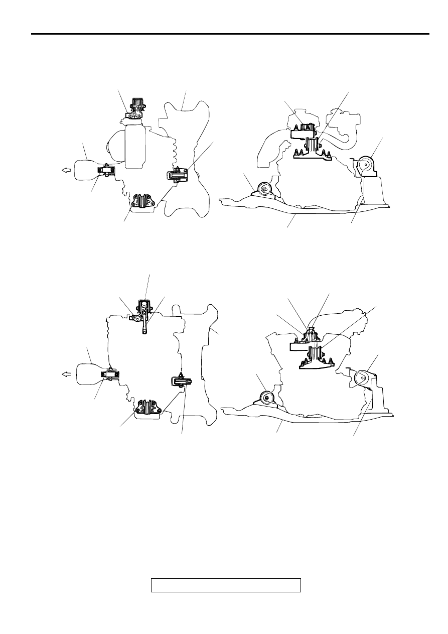
POWER PLANT MOUNT
32-3
ENGINE MOUNT CONSTRUCTION DIAGRAM
AC000298
FRONT
FRONT
ENGINE MOUNT
ENGINE MOUNT
ENGINE MOUNT
ENGINE MOUNT
CROSSMEMBER
CROSSMEMBER
CROSSMEMBER
CROSSMEMBER
CENTERMEMBER
CENTERMEMBER
CENTERMEMBER
CENTERMEMBER
FRONT ROLL
STOPPER
FRONT ROLL
STOPPER
FRONT ROLL
STOPPER
FRONT ROLL STOPPER
TRANSAXLE MOUNT
TRANSAXLE MOUNT
TRANSAXLE MOUNT
TRANSAXLE
MOUNT
REAR ROLL
STOPPER
REAR ROLL
STOPPER
REAR ROLL
STOPPER
REAR ROLL
STOPPER
DYNAMIC DAMPER
DYNAMIC DAMPER
ENGINE MOUNT STAY
ENGINE
MOUNT
STAY
<2.4L ENGINE>
<3.0L ENGINE>
AB