Mitsubishi Eclipse / Eclipse Spyder (2000-2002). Service and repair manual - part 516


  Index      Mitsubishi     Mitsubishi Eclipse / Eclipse Spyder (2000-2002). Service and repair manual


Search            


Content   ..  514  515  516  517   ..


Mitsubishi Eclipse / Eclipse Spyder (2000-2002). Service and repair manual - part 516


TRANSAXLE ASSEMBLY

TSB Revision

AUTOMATIC TRANSAXLE

23A-356

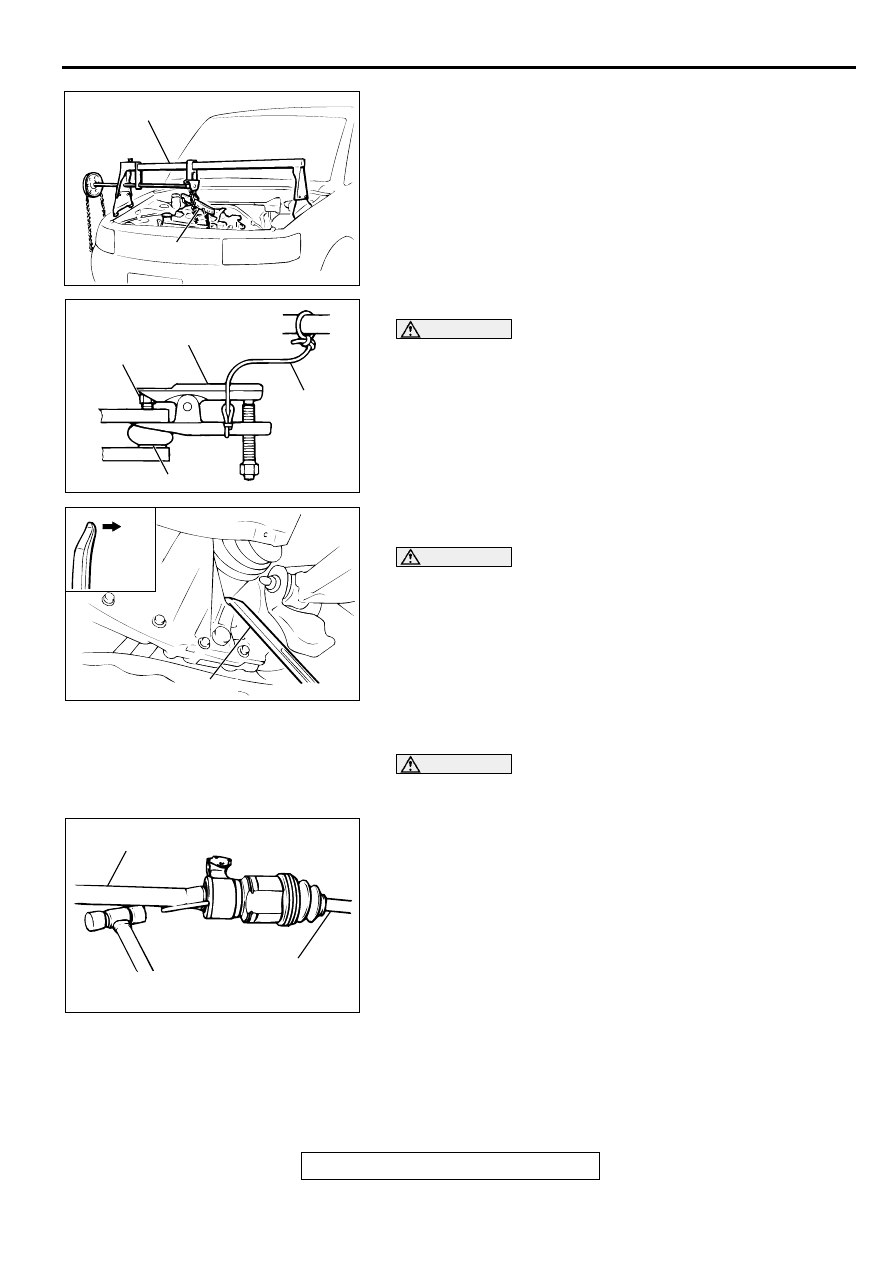
<<C>> ENGINE ASSEMBLY SUPPORTING
Set special tools MB991453 and MZ203827 to the vehicle to 
support the engine assembly.

<<D>> TIE ROD END/LOWER ARM DISCONNECTION

CAUTION

Before using special tool MB991113 or MB990635, 
loosen the tie rod end mounting nut. Only loosen the 
nut; do not remove it from the ball joint.

Support special tool MB991113 or MB990635 with a 
cord, etc. to prevent it from coming off.

<<E>> DRIVE SHAFT/DRIVE SHAFT AND INNER SHAFT 
DISCONNECTION

CAUTION

Do not pull on the drive shaft; doing so will damage the 
TJ; be sure to use a pry bar.

Do not insert the pry bar so deep as to damage the oil 
seal.

Do not damage the transaxle oil seal with the spline of 
the drive shaft.

1. Insert the pry bar between the transaxle case and the drive- 

shaft as shown to remove the drive shaft. <2.4L ENGINE, 
3.0L ENGINE-LH>

CAUTION

Do not damage the transaxle oil seal with the spline of the 
inner shaft.
2. If the inner shaft and transaxle are tightly joined, tap the 

center bearing bracket lightly with a plastic hammer, etc. to 
remove the drive shaft and inner shaft from the transaxle. 
<3.0L ENGINE-RH>

3. Cover the transaxle case with a shop towel to prevent 

foreign material from entering it.

AC001641AB

MZ203827

MB991453

AC001642AB

CORD

BALL JOINT

MB991113 
or MB990635

NUT

AC001643AB

TRANS-
AXLE
SIDE

PRY BAR

AC001644AB

INNER SHFT

DRIVE SHAFT

TRANSAXLE ASSEMBLY

TSB Revision

AUTOMATIC TRANSAXLE

23A-357

<<F>> DRIVE PLATE BOLTS/TRANSAXLE ASSEMBLY 
LOWER PART COUPLING BOLTS/TRANSAXLE ASSEMBLY 
REMOVAL
1. Support the transaxle assembly by using a transaxle jack.

2. Remove the drive plate bolts while turning the crank shaft.

3. Press in the torque converter to the transaxle side so that 

the torque converter does not stay engaged to the drive 
plate.

4. Remove the transaxle assembly lower bolts and lower the 

transaxle assembly.

INSTALLATION SERVICE POINTS

>>A<< TRANSAXLE ASSEMBLY INSTALLATION
Inserting the torque converter into the transaxle oil pump so 
that the shown dimension is approximately. 12.2 mm (0.48 
inch) <2.4L ENGINE>, approximately 9.4 mm (0.37 inch) <3.0L 
ENGINE>. Install the transaxle assembly to the engine.

>>B<< TRANSAXLE MOUNT STOPPER INSTALLATION
Install the transaxle mount stopper so that the arrow mark 
points as shown in the illustration.

AC001645AB

DRIVE PLATE BOLT

AC001646AB

APPROXMATELY
12.2 mm (0.48 in)
<2.4L ENGINE>
9.4 mm (0.37 in)
<3.0L ENGINE>

AC001647AB

TRANSAXLE
MOUNT
STOPPER

ENGINE SIDE

ARROW

TRANSAXLE
MOUNT
BRACKET

SPECIFICATIONS

TSB Revision

AUTOMATIC TRANSAXLE

23A-358

SPECIFIC ATIO NS

FASTENER TIGHTENING SPECIFICATIONS

M1231012400052

ITEMS

SPECIFICATIONS

Key interlock cable 

12 

±

 2 N

 m (102 

±

 22 in-lb)

Shift lock cable

12 

±

 2 N

 m (102 

±

 22 in-lb)

Transaxle assembly

Bell housing cover <2.4L engine>

To engine

8.8 

±

 1.0 N

 m (78 

±

 8 in-lb)

To transaxle

26 

±

 4 N

 m (19 

±

 3 ft-lb)

Centermember assembly

Front

93 

±

 15 N

 m (69 

±

 11 ft-lb)

Front roll stopper

45 

±

 10 N

 m (33 

±

 7 ft-lb)

Rear

74 

±

 4 N

 m (53 

±

 3 ft-lb)

Drive plate bolt

49 

±

 3 N

 m (37 

±

 2 ft-lb)

Drive shaft and inner shaft <3.0L engine>

40 

±

 5 N

 m (30 

±

 3 ft-lb)

Lower arm connection

108 

±

 10 N

 m (80 

±

 7 ft-lb)

Rear roll stopper bracket

45 

±

 5 N

 m (34 

±

 3 ft-lb)

Starter motor

30 

±

 3 N

 m (23 

±

 2 ft-lb)

Starter cover mounting bolt <2.4L engine>

4.9 

±

 1.0 N

 m (44 

±

 8 in-lb)

Stabilizer link connection

44 

±

 10 N

 m (33 

±

 7 ft-lb)

Tie rod end connection

29 

±

 4 N

 m (21 

±

 4 ft-lb)

Transaxle assembly lower part 
coupling bolt

2.4L engine

48 

±

 6 N

 m (36 

±

 4 ft-lb)

3.0L engine

71 

±

 12 N

 m (52 

±

 9 ft-lb)

Transaxle assembly upper part 
coupling bolt

2.4L engine

48 

±

 6 N

 m (36 

±

 4 ft-lb)

3.0L engine

Bolt, flange

71 

±

 12 N

 m (52 

±

 9 ft-lb)

Bolt, washer assembled 88 

±

 10 N

 m (65 

±

 7 ft-lb)

Transaxle control cable connection

12 

±

 2 N

 m (102 

±

 22 in-lb)

Transaxle mount bracket

57 

±

 7 N

 m (42 

±

 5 ft-lb)

Transaxle mount stopper

83 

±

 12 N

 m (61 

±

 9 ft-lb)

Transaxle control

Cable arm <vehicles with sport mode>

12 

±

 2 N

 m (102 

±

 22 in-lb)

Detente spring <vehicles without sport mode>

1.5 

±

 0.5 N

 m (14 

±

 4 in-lb)

Indicator panel assembly

1.5 

±

 0.5 N

 m (14 

±

 4 in-lb)

Key interlock cable connection

12 

±

 2 N

 m (102 

±

 22 in-lb)

Lever assembly <vehicles without sport mode>

12 

±

 2 N

 m (102 

±

 22 in-lb)

Nut 

12 

±

 2 N

 m (102 

±

 22 in-lb)

Shift lock cable connection

12 

±

 2 N

 m (102 

±

 22 in-lb)

Shift knob

1.8 

±

 0.2 N

 m (16 

±

 2 in-lb)

Shift switch <vehicles with sport mode>

5.0 

±

 1.0 N

 m (44 

±

 9 in-lb)

Select lever <vehicles with sport mode>

12 

±

 2 N

 m (102 

±

 22 in-lb)

Selector lever assembly

12 

±

 2 N

 m (102 

±

 22 in-lb)

Transaxle control cable assembly

12 

±

 2 N

 m (102 

±

 22 in-lb)

SPECIFICATIONS

TSB Revision

AUTOMATIC TRANSAXLE

23A-359

SERVICE SPECIFICATIONS

M1231000300047

LUBRICANTS

M1231000400044

ITEMS

STANDARD VALUE

Line pressure kPa (psi)

1,010 

 1,050 (147 

 152)

A/T fluid temperature sensor k

at 0

°

C (32

°

F)

16.7 

 20.5

at 20

°

C (68

°

F)

7.3 

 8.9

at 40

°

C (104

°

F)

3.4 

 4.2

at 60

°

C (140

°

F)

1.9 

 2.2

at 80

°

C (176

°

F)

1.0 

 1.2

at 100

°

C (212

°

F)

0.57 

 0.69

Resistance of torque converter clutch control solenoid valve coil [at 20

°

(68

°

F)] 

2.7 

 3.4

Resistance of low-reverse solenoid valve coil [at 20

°

C (68

°

F)] 

2.7 

 3.4

Resistance of second solenoid valve coil [at 20

°

C (68

°

F)] 

2.7 

 3.4

Resistance of underdrive solenoid valve coil [at 20

°

C (68

°

F)] 

2.7 

 3.4

Resistance of overdrive solenoid valve coil [at 20

°

C (68

°

F)] 

2.7 

 3.4

Stall speed r/min

2,100 

 2,600

ITEMS

SPECIFIED LUBRICANTS

QUANTITY

A/T fluid dm

3

 (qt)

F4A42

DIAMOND ATF SP-III, DIAMOND ATF 
SP-II M or equivalent

7.7 (8.1)

F4A51

8.4 (8.9)


Content   ..  514  515  516  517   ..