Mitsubishi Eclipse / Eclipse Spyder (2000-2002). Service and repair manual - part 503


  Index      Mitsubishi     Mitsubishi Eclipse / Eclipse Spyder (2000-2002). Service and repair manual


Search            


Content   ..  501  502  503  504   ..


Mitsubishi Eclipse / Eclipse Spyder (2000-2002). Service and repair manual - part 503


AUTOMATIC TRANSAXLE DIAGNOSIS

TSB Revision

AUTOMATIC TRANSAXLE

23A-304

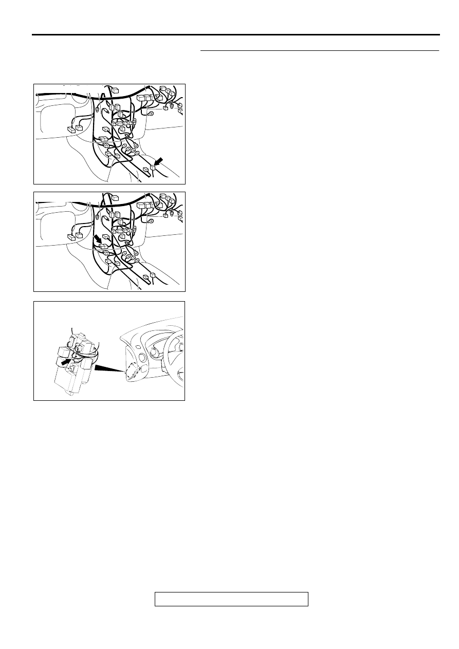
STEP 5. Check connectors C-65 at shift switch assembly, 
C-28 at intermediate connector and C-107 at junction block 
for damage.
Q: Are the connectors in good condition?

YES : Go to Step 6.
NO :  Repair or replace it. Refer to GROUP 00E, Harness 

Connector Inspection 

P.00E-2

.

AC001741

CONNECTOR: C-65

AP

AC001741

CONNECTOR: C-28

AM

AC001691

CONNECTOR: C-107

JUNCTION BLOCK
(FRONT VIEW)

AO

AUTOMATIC TRANSAXLE DIAGNOSIS

TSB Revision

AUTOMATIC TRANSAXLE

23A-305

STEP 6. Check harness for open circuit or short circuit to 
ground between shift switch assembly connector C-65 
terminal 3 and junction block connector C-107 terminal 9.
Q: Is the harness wire in good condition?

YES : Go to Step 3.
NO :  Repair it.

STEP 7. Using scan tool MB991502, check data list item 61: 
Park/Neutral Position Switch.

CAUTION

To prevent damage to scan tool MB991502, always turn the 
ignition switch to "LOCK" (OFF) position before 
connecting or disconnecting scan tool MB991502. 
(1) Connect scan tool MB991502 to the data link connector.
(2) Turn the ignition switch to "ON" position.
(3) Set scan tool MB991502 to data reading mode for item 61: 

Park/Neutral Position Switch.

The scan tool should display "D" when the selector lever 
is "D" range.

(4) Turn the ignition switch to "LOCK" (OFF) position.

Q: Is the switch operating properly?

YES : Go to Step 8.
NO :  Go to Step 15.

STEP 8. Check the shift switch assembly.
Refer to 

P.23A-351

, Transaxle Control.

Q: Is the switch operating properly?

YES : Go to Step 9.
NO :  Replace the shift switch assembly. Refer to 

P.23A-

349

Transaxle Control.

AC001741

CONNECTOR: C-65

AP

AC001691

CONNECTOR: C-107

JUNCTION BLOCK
(FRONT VIEW)

AO

AC001252AE

16 PIN

MB991502

AUTOMATIC TRANSAXLE DIAGNOSIS

TSB Revision

AUTOMATIC TRANSAXLE

23A-306

STEP 9. Check connector C-65 at shift switch assembly for 
damage.
Q: Is the connector in good condition?

YES : Go to Step 10.
NO :  Repair or replace it. Refer to GROUP 00E, Harness 

Connector Inspection 

P.00E-2

.

STEP 10. Check the power supply voltage at shift switch 
assembly connector C-65.
(1) Disconnect connector C-65 and measure at the harness 

side.

(2) Turn the ignition switch to "ON" position.
(3) Selector lever position should be "D" range.

(4) Measure the voltage between terminal 1 and ground.

Voltage should be battery positive voltage.

(5) Turn the ignition switch to "LOCK" (OFF) position.

Q: Is the voltage normal?

YES : Go to Step 12.
NO :  Go to Step 11.

STEP 11. Check connector B-41 at Park/Neutral position 
switch for damage.
Q: Is the connector in good condition?

YES : Repair it because of harness open circuit between 

shift switch assembly connector C-65 terminal 1 and 
Park/Neutral position switch connector B-41 terminal 
3.

NO :  Repair or replace it. Refer to GROUP 00E, Harness 

Connector Inspection 

P.00E-2

.

AC001741

CONNECTOR: C-65

AP

AC001741

CONNECTOR: C-65

AP

ACX02187

HARNESS
CONNECTOR: C-65

AD

AC001844

CONNECTOR: B-41

DIPSTICK

AB

AUTOMATIC TRANSAXLE DIAGNOSIS

TSB Revision

AUTOMATIC TRANSAXLE

23A-307

STEP 12. Check the switch output voltage at PCM 
connector C-61 <2.4L Engine> or C-63 <3.0L Engine> by 
backprobing.
(1) Do not disconnect connector C-61 <2.4L Engine> or C-63 

<3.0L Engine>.

(2) Turn the ignition switch to "ON" position.
(3) Selector lever position should be sport mode.

(4) Measure the voltage between terminal 109 and ground by 

backprobing.

Voltage should be battery positive voltage.

(5) Turn the ignition switch to "LOCK" (OFF) position.

Q: Is the voltage normal?

YES : Go to Step 14.
NO :  Go to Step 13.

STEP 13. Check connectors C-61 <2.4L Engine> or C-63 
<3.0L Engine> at PCM connector for damage.
Q: Are the connectors in good condition?

YES : Repair it because of harness open circuit or short 

circuit to ground between shift switch assembly 
connector C-65 terminal 4 and PCM connector C-61 
<2.4L Engine> or C-63 <3.0L Engine> terminal 109.

NO :  Repair or replace it. Refer to GROUP 00E, Harness 

Connector Inspection 

P.00E-2

.

STEP 14. Check connector C-61 <2.4L Engine> or C-63 
<3.0L Engine> at PCM for damage.
Q: Is the connector in good condition?

YES : Go to Step 3.
NO :  Repair or replace it. Refer to GROUP 00E, Harness 

Connector Inspection 

P.00E-2

.

AC001657

CONNECTOR: C-61 <2.4L ENGINE> OR
C-63 <3.0L ENGINE>

PCM

AN

AC002122

C-61 <2.4L ENGINE> OR C-63 
<3.0L ENGINE> CONNECTOR 
HARNESS SIDE VIEW

AD

AC001657

CONNECTOR: C-61 <2.4L ENGINE> OR
C-63 <3.0L ENGINE>

PCM

AN

AC001657

CONNECTOR: C-61 <2.4L ENGINE> OR
C-63 <3.0L ENGINE>

PCM

AN


Content   ..  501  502  503  504   ..