Mitsubishi Eclipse / Eclipse Spyder (2000-2002). Service and repair manual - part 484


  Index      Mitsubishi     Mitsubishi Eclipse / Eclipse Spyder (2000-2002). Service and repair manual


Search            


Content   ..  482  483  484  485   ..


Mitsubishi Eclipse / Eclipse Spyder (2000-2002). Service and repair manual - part 484


AUTOMATIC TRANSAXLE DIAGNOSIS

TSB Revision

AUTOMATIC TRANSAXLE

23A-228

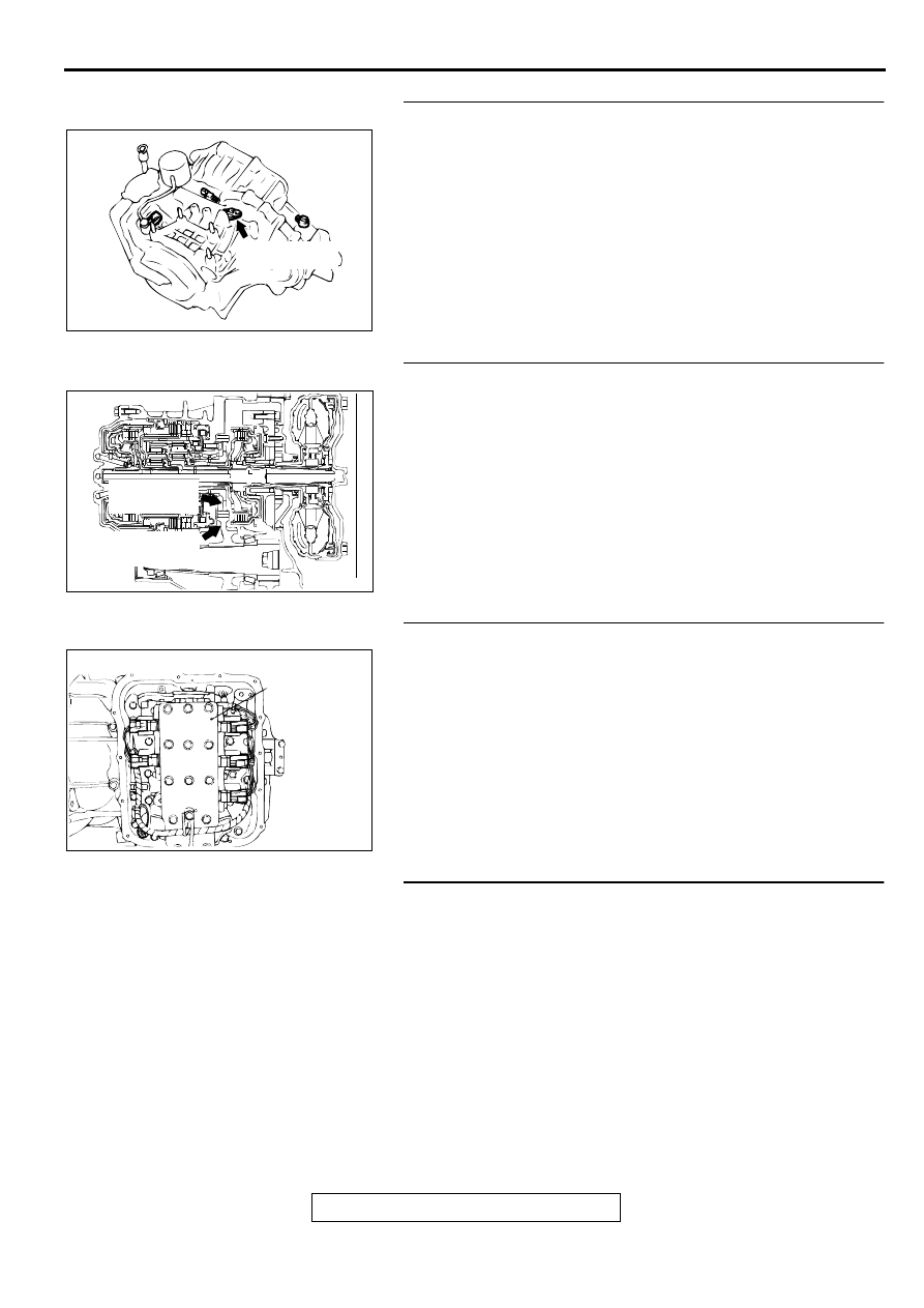
STEP 11. Replace the output shaft speed sensor.
(1) Replace the output shaft speed sensor. Refer to GROUP 

23B, Transaxle 

P.23B-11

.

(2) Carry out a test drive.
(3) Read in the A/T diagnostic trouble code (DTC).

Q: Is the A/T diagnostic trouble code output?

YES : Go to Step 12.
NO :  The inspection is complete.

STEP 12. Replace the transfer drive gear or driven gear.
(1) Replace the output shaft. Refer to GROUP 23B, Transaxle, 

Output Shaft 

P.23B-11

.

(2) Carry out a test drive.
(3) Read in the A/T diagnostic trouble code.

Q: Is the A/T diagnostic trouble code output?

YES : The A/T diagnostic trouble code may have set due to 

external radio frequency (RFI), possibly caused by 
cellular phone activity, after market components 
installed on the vehicle, etc.

NO :  The inspection is complete.

STEP 13. Replace the valve body.
(1) Replace the valve body. Refer to GROUP 23B, Transaxle 

P.23B-11

.

(2) Carry out a test drive.
(3) Read in the A/T diagnostic trouble code.

Q: Is the A/T diagnostic trouble code output?

YES : Go to Step 14.
NO :  The inspection is complete.

STEP 14. Replace the PCM.
(1) Replace the PCM.
(2) Carry out a test drive.
(3) Read in the diagnostic trouble code.

Q: Is the A/T diagnostic trouble code output?

YES : Go to Step 15.
NO :  The inspection is complete.

AC001837AD

OUTPUT SHAFT
SPEED SENSOR

AC002221AC

TRANSFER
DRIVE GEAR

TRANSFER
DRIVEN GEAR

AC001860 AB

VALVE
BODY
ASSEMBLY

AUTOMATIC TRANSAXLE DIAGNOSIS

TSB Revision

AUTOMATIC TRANSAXLE

23A-229

STEP 15. Overhaul the A/T.
(1) Replace the following parts.

Replace the underdrive clutch. Refer to GROUP 23B, 
Underdrive Clutch 

P.23B-52

(When the codes of No.41, 

No.42, No.43 are output individually or in plural.)

Replace the overdrive clutch. Refer to GROUP 23B, 
Reverse and Overdrive Clutches 

P.23B-54

(When the 

codes of No.43, No.44 are output individually or in 
plural.)

Replace the reverse clutch. Refer to GROUP 23B, 
Reverse and Overdrive Clutches 

P.23B-54

(When the 

code of No.46 is output.)

Replace the low-reverse brake. Refer to GROUP 23B, 
Transaxle 

P.23B-11

. (When the codes of No.41 and 

No.46 are output.)

Replace the second brake. Refer to GROUP 23B, 
Transaxle 

P.23B-11

. (When the codes of No.42 and 

No.44 are output.)

Replace the one-way clutch (OWC-L). Refer to GROUP 
23B, Low Reverse Annulus Gear 

P.23B-61

. (When the 

code of No.41 is output individually.)

(2) Carry out a test drive.
(3) Read in the A/T diagnostic trouble code.

Q: Is the A/T diagnostic trouble code output again?

YES : The A/T diagnostic trouble code may have set due to 

external radio frequency (RFI), possibly caused by 
cellular phone activity, after market components 
installed on the vehicle, etc.

NO :  The inspection is complete.

DTC 52: Torque Coverter Clutch System

DTC SET CONDITIONS
If input shaft speed sensor is abnormal and drive 
duty rate for the torque converter clutch solenoid 
valve is 100 percent for continuous period of 4 
seconds or more, it is judged that there is an 
abnormality in the torque converter clutch system 
and diagnostic trouble code number "52" is output.

TROUBLESHOOTING HINTS (The most likely 

causes for this code to be set:)

Malfunction of the torque converter clutch 
solenoid valve

Damaged harness, connector

Malfunction of the PCM

Malfunction of the underdrive clutch

DIAGNOSIS

Required Special Tool:
MB991502: Scan Tool (MUT-II)

AC001868

REVERSE
CLUTCH

SECOND
BRAKE

LOW-
REVERSE
BRAKE

UNDERDRIVE
CLUTCH

OVERDRIVE CLUTCH

AB

AUTOMATIC TRANSAXLE DIAGNOSIS

TSB Revision

AUTOMATIC TRANSAXLE

23A-230

STEP 1. Using scan tool MB991502, read the A/T 
diagnostic trouble code.

CAUTION

To prevent damage to scan tool MB991502, always turn the 
ignition switch to "LOCK" (OFF) position before 
connecting or disconnecting scan tool MB991502.
(1) Connect scan tool MB991502 to the data link connector.
(2) Turn the ignition switch to "ON" position.
(3) Read the A/T diagnostic trouble code.
(4) Turn the ignition switch to "LOCK" (OFF) position.

Q: Is A/T diagnostic trouble code number "22" output?

YES : Refer to 

P.23A-103

, code number 22: Input Shaft 

Speed Sensor System.

NO :  Go to Step 2.

STEP 2. Using scan tool MB991502, check actuator test 
item 06: Torque Converter Clutch Solenoid Valve.
(1) Connect scan tool MB991502 to the data link connector.
(2) Turn the ignition switch to "ON" position.
(3) Set scan tool MB991502 to actuator test mode for item 06: 

Torque Converter Clutch Solenoid Valve.

An operation sound should be heard from solenoid 
valve when the torque converter clutch solenoid valve is 
operated.

(4) Turn the ignition switch to "LOCK" (OFF) position.

Q: Is the solenoid valve operating properly?

YES : Go to Step 3..
NO :  Replace the torque converter clutch solenoid valve. 

Refer to GROUP 23B, Valve Body 

P.23B-69

.

AC001252

MB991502

16 PIN

AB

AC001252

MB991502

16 PIN

AB

AUTOMATIC TRANSAXLE DIAGNOSIS

TSB Revision

AUTOMATIC TRANSAXLE

23A-231

STEP 3. Using the oscilloscope, check the waveform at 
PCM connectors C-54 <2.4L Engine> or C-55 <3.0L 
Engine> and C-61 <2.4L Engine> or C-63 <3.0L Engine> by 
backprobing.
(1) Do not disconnect connectors C-54 <2.4L Engine> or C-55 

<3.0L Engine> and C-61 <2.4L Engine> or C-63 <3.0L 
Engine>.

(2) Connect an oscilloscope probe to PCM connector C-54 

<2.4L Engine> or C-55 <3.0L Engine> terminal 57 and to 
PCM connector C-61 <2.4L Engine> or C-63 <3.0L Engine> 
terminal 103 by backprobing.

(3) Start the engine and run at constant speed of 50km/h 

(31mph). (Gear range: 3rd gear)

(4) Check the waveform.

The waveform should show a pattern similar to the 
illustration. The maximum value should be 4.8 volts and 
more and the minimum value 0.8 volts and less. The 
output waveform should not contain the noise.

(5) Turn the ignition switch to "LOCK" (OFF) position.

Q: Is the waveform normal?

YES : Go to Step 8.
NO :  Go to Step 4.

AC001657

CONNECTORS: C-54 <2.4L ENGINE> OR
C-55 <3.0L ENGINE>, C-61 <2.4L ENGINE>
OR C-63 <3.0L ENGINE>

PCM

AM

C-54 <2.4L ENGINE> 
OR
C-55 <3.0L ENGINE>

C-61 <2.4L ENGINE>
OR 
C-63 <3.0L ENGINE>

AC001899

C-61 <2.4L ENGINE> OR C-63 <3.0L ENGINE>
CONNECTOR HARNESS  SIDE VIEW

C-54 <2.4L ENGINE> OR C-55 <3.0L ENGINE>
CONNECTOR HARNESS SIDE VIEW

AD

OSCILLO-
SCOPE

PROBE

ACX02131AB

NORMAL WAVEFORM

(V)

5

0


Content   ..  482  483  484  485   ..