Mitsubishi Eclipse / Eclipse Spyder (2000-2002). Service and repair manual - part 408


  Index      Mitsubishi     Mitsubishi Eclipse / Eclipse Spyder (2000-2002). Service and repair manual


Search            


Content   ..  406  407  408  409   ..


Mitsubishi Eclipse / Eclipse Spyder (2000-2002). Service and repair manual - part 408


TRANSAXLE ASSEMBLY

TSB Revision

MANUAL TRANSAXLE

22A-17

Required Special Tools:

MB991113: Steering Linkage Puller

MB991453: Engine Hanger Assembly

MZ203827: Engine Lifter

REMOVAL SERVICE POINTS

<<A>> STARTER MOTOR REMOVAL
Remove the starter motor with the starter motor harness still 
connected and secure it inside the engine compartment.

<<B>> CLUTCH RELEASE CYLINDER REMOVAL
Remove the clutch release cylinder without disconnecting the 
oil line connection, and fix it to the vehicle chassis.

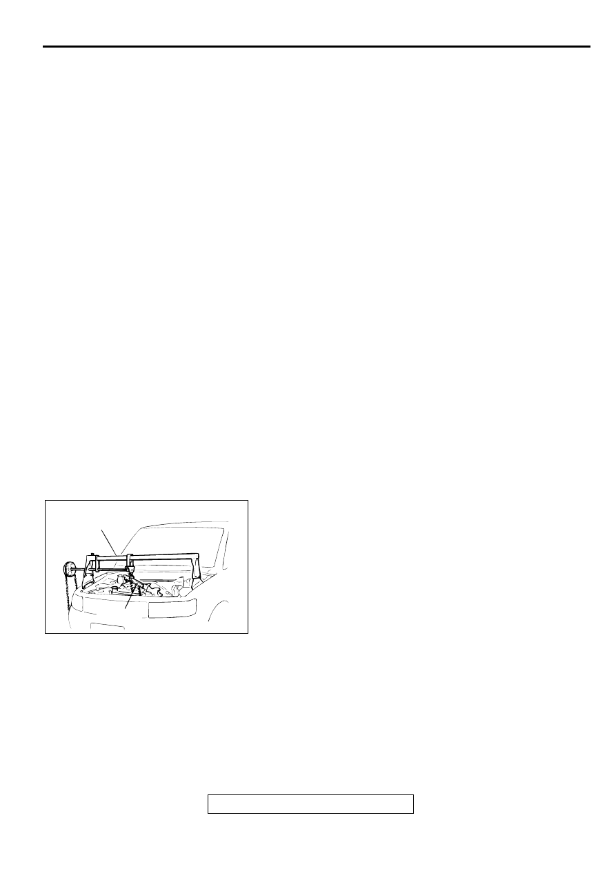
<<C>> CENTERMEMBER ASSEMBLY REMOVAL
Set the special tools MB991453 and MZ203827 to the vehicle 
to support the engine assembly.

<<D>> TRANSAXLE MOUNT BRACKET REMOVAL
Jack up the transaxle assembly gently with a garage jack, and 
then remove the transaxle mount bracket.

REMOVAL STEPS

1.

SHIFT CABLE AND SELECT 
CABLE CONNECTION (REFER 
TO 

P.22A-10

.)

2.

BACKUP LIGHT SWITCH 
CONNECTOR

3.

VEHICLE SPEED SENSOR 
CONNECTOR

<<A>>

4.

STARTER MOTOR

<<B>>

5.

CLUTCH RELEASE CYLINDER 
CONNECTION

6.

TRANSAXLE ASSEMBLY UPPER 
PART COUPLING BOLTS

<<C>>

7.

CENTERMEMBER ASSEMBLY

8.

REAR ROLL STOPPER

<<D>>

9.

TRANSAXLE MOUNT BRACKET

>>C<<

10. TRANSAXLE MOUNT STOPPER
11. STABILIZER LINK CONNECTION 

<STRUT SIDE>

12. WHEEL SPEED SENSOR CABLE 

CONNECTION <VEHICLES 
WITH ABS>

13. BRAKE HOSE CLAMP

<<E>>

14. TIE ROD END CONNECTION

<<E>>

15. LOWER ARM CONNECTION

<<F>>

>>B<<

CLUTCH RELEASE BEARING 
ENGAGEMENT

<<G>>

16. DRIVESHAFT CONNECTION

<<G>>

17. DRIVESHAFT AND INNER 

SHAFT CONNECTION

18. UPPER OIL PAN CONNECTING 

BOLT

19. TRANSAXLE ASSEMBLY 

LOWER PART COUPLING 
BOLTS

<<H>>

>>A<<

20. TRANSAXLE ASSEMBLY

REMOVAL STEPS (Continued)

ACX00406

MZ203827

AB

MB991453

TRANSAXLE ASSEMBLY

TSB Revision

MANUAL TRANSAXLE

22A-18

<<E>> TIE ROD END/LOWER ARM BALL JOINT 
DISCONNECTION

CAUTION

Use special tool MB991113 to loosen the tie rod end 
mounting nut. Only loosen the nut; do not remove it from 
the ball joint.

CAUTION

Support special tool MB991113 with a cord, etc., to prevent 
it from coming off.

<<F>> CLUTCH RELEASE BEARING DISENGAGEMENT

1. Remove the service hole plug at the clutch housing.

2. Insert a flat-tipped screwdriver into space between the 

release bearing and the wedge collar while pushing the 
release fork to the "A" direction by hand slightly.

CAUTION

Do not insert the screwdriver before pushing the release 
fork to the "A" direction. 

3. Disengage the wedge collar from the release bearing by 

using the flat-tipped screwdriver to pry gently (twisting the 
screwdriver handle 90 degree).

NOTE: If the release bearing is disengaged, the release fork 
will move fully to the 

CAUTION

If the screwdriver cannot be twisted easily (the release 
bearing cannot be disengaged), remove the screwdriver, 
and push the release fork to the "A" direction two or three 
times to try again. If the clutch release bearing is pried 
forcibly, it will be damaged. 

ACX00715AC

BALL JOINT

CORD

NUT

MB991113 OR
MB990635

AC001668 AB

A

B

RELEASE BEARING

SERVICE 
HOLE

RELEASE FORK

WEDGE
COLLAR

TRANSAXLE ASSEMBLY

TSB Revision

MANUAL TRANSAXLE

22A-19

<<G>> DRIVESHAFT/DRIVESHAFT AND INNER SHAFT 
DISCONNECTION

CAUTION

Do not pull on the drive shaft; doing so will damage the 
TJ; be sure to use a pry bar.

Do not insert a pry bar so deep as to damage the oil 
seal.

Do not damage the transaxle oil seal with the spline of 
the drive shaft.

<2.4L ENGINE, 3.0L ENGINE 

 LH>

1. Insert a pry bar between the transaxle case and the drive 

shaft as shown to remove the drive shaft.

CAUTION

Do not damage the transaxle oil seal with the spline of the 
inner shaft.
<3.0L ENGINE 

 RH>

2. If the inner shaft and transaxle are tightly joined, tap the 

center bearing bracket lightly with a plastic hammer, etc. to 
remove the drive shaft and inner shaft from the transaxle.

3. Cover the transaxle case with a shop towel to prevent 

foreign material from entering it.

<<H>> TRANSAXLE ASSEMBLY REMOVAL

CAUTION

Do not remove the flywheel mounting bolt shown by the 
arrow. If this bolt is removed, the flywheel will become out 
of balance and damaged.

AC001157

TRANS-
AXLE
SIDE

AB

PRY BAR

AC001158

AC001669

BOLT

AB

FLYWHEEL

TRANSAXLE ASSEMBLY

TSB Revision

MANUAL TRANSAXLE

22A-20

INSTALLATION SERVICE POINTS

>>A<< TRANSAXLE ASSEMBLY INSTALLATION

CAUTION

On the pull-type clutch, do not roll the transaxle assembly 
when installing it to the engine. If the transaxle assembly 
is rolled, the wedge collar and the wire ring will be 
deformed, causing a clutch malfunction due to improper 
engagement of the wedge collar and the wire ring.

AC001670

ENGINE SIDE

TRANSAXLE SIDE

FLYWHEEL

CLUTCH COVER

WEDGE
COLLAR

RELEASE
BEARING

WIRE RING

AB


Content   ..  406  407  408  409   ..