Mitsubishi Eclipse / Eclipse Spyder (2000-2002). Service and repair manual - part 376


  Index      Mitsubishi     Mitsubishi Eclipse / Eclipse Spyder (2000-2002). Service and repair manual


Search            


Content   ..  374  375  376  377   ..


Mitsubishi Eclipse / Eclipse Spyder (2000-2002). Service and repair manual - part 376


AUTO-CRUISE CONTROL

TSB Revision

ENGINE AND EMISSION CONTROL

17-23

STEP 7. Check auto-cruise control vacuum pump 
connector A-01 and intermediate connector C-06.
Q: Is any connector damaged?

YES : Repair or replace connector. 

Refer to GROUP 00E, Harness Connector Inspection 

P.00E-2

Then check that diagnostic trouble code 14 is not 
output.

NO :  Check the harness wire between stoplight switch 

connector C-03 and auto-cruise control vacuum pump 
connector A-01 for open circuit or damage. 
Then repair if necessary. 
Then check that diagnostic trouble code 14 is not 
output.

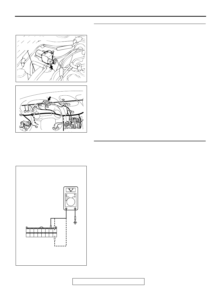
STEP 8. Check the output circuit voltage at auto-cruise 
control-ECU connector C-20 by backprobing.
(1) Do not disconnect auto-cruise control-ECU connector C-20.
(2) Turn the ignition switch to "ON" position and the auto-cruise 

control main switch to "ON" position.

(3) Measure the voltage between terminal 7 and ground by 

backprobing.

Voltage should be battery positive voltage.
 [When decelerating with the "SET" switch while driving 
at constant speed (Release valve open).]

(4) Measure the voltage between terminal 8 and ground by 

backprobing.

Voltage should be battery positive voltage.
 [When decelerating with the "SET" switch while driving 
at constant speed. (Control valve open).]

(5) Measure the voltage between terminal 16 and ground by 

backprobing.

Voltage should be battery positive voltage.
 (When the motor is stopped during a constant road 
speed.)

(6) Turn the ignition switch to "LOCK" (OFF) position.

Q: Are all of the above values satisfied?

YES : Check that diagnostic trouble code 14 is not output. 

If diagnostic trouble code 14 is output, replace the 
auto-cruise control-ECU. (Refer to 

P.17-81

.) 

Then check that diagnostic trouble code 14 is not.

NO :  Go to Step 9.

AC001449

CONNECTOR: A-01

RESERVE
TANK

AB

AC003552 AB

CONNECTOR: C-06

1 2 3 4 5 6 7 8

9 10 11 12 13 14 15 16

ACX01897

C-20 CONNECTOR
HARNESS SIDE VIEW

AF

AUTO-CRUISE CONTROL

TSB Revision

ENGINE AND EMISSION CONTROL

17-24

STEP 9. Check auto-cruise control-ECU connector C-20 
and intermediate connector C-94.
Q: Is the connector damaged?

YES : Repair or replace connector. 

Refer to GROUP 00E, Harness Connector Inspection 

P.00E-2

Then check that diagnostic trouble code 14 is not 
output.

NO :  Go to Step 10.

STEP 10. Check auto-cruise control vacuum pump 
connector A-01.
Q: Is the connector damaged?

YES : Repair or replace connector. 

Refer to GROUP 00E, Harness Connector Inspection 

P.00E-2

Then check that diagnostic trouble code 14 is not 
output.

NO :  Go to Step 11.

AC001451

CONNECTOR: C-20

AB

AC001992

CONNECTOR: C-94

AF

CONNECTOR
BLOCK (RH)

AC001449

CONNECTOR: A-01

RESERVE
TANK

AB

AUTO-CRUISE CONTROL

TSB Revision

ENGINE AND EMISSION CONTROL

17-25

STEP 11. Check the auto-cruise vacuum pump.
(1) Disconnect the vacuum hose from the auto-cruise vacuum 

pump and connect a vacuum gauge to the vacuum pump.

(2) Disconnect the vacuum pump connector.
(3) Check the auto-cruise vacuum pump and valves according 

to the following procedure:

Connect the positive battery terminal to auto-cruise 
vacuum pump connector terminal 1, and the negative 
battery terminal to terminals 2, 3, and 4. 
The vacuum gauge should read 27 kPa (8.0 in Hg) or 
more.

The vacuum should be maintained when terminal 4 is 
disconnected from the negative battery terminal while 
terminals 1, 2, and 3 remain connected. 
Then the vacuum gauge should read 0 kPa (0 in Hg) 
when terminal 2 is disconnected from the negative 
battery terminal while terminals 1, and 3 remain 
connected.

The vacuum should be maintained when terminal 4 is 
disconnected from the negative battery terminal while 
terminals 1, 2, and 3 remain connected. 
Then the vacuum gauge should read 0 kPa (0 in Hg) 
when terminal 3 is disconnected from the negative 
battery terminal while terminals 1, and 2 remain 
connected.

Q: Are all of the above values satisfied?

YES : Go to Step 12.
NO :  Replace the auto-cruise vacuum pump. (Refer to 

P.17-81

.)

Then check that diagnostic trouble code 14 is not 
output.

ACX01181AB

VACUUM 
GAUGE

CONTROL
VALVE

RELEASE
VALVE

AUTO-CRUISE CONTROL

TSB Revision

ENGINE AND EMISSION CONTROL

17-26

STEP 12. Check the harness wire between auto-cruise 
control vacuum pump connector A-01 and auto-cruise 
control-ECU connector C-20.
Q: Is any harness wire between auto-cruise control 

vacuum pump connector A-01 and auto-cruise control-
ECU connector C-20 damaged?
YES : 
Repair harness wire and then check that diagnostic 

trouble code 14 is not output.

NO :  Check that diagnostic trouble code 14 is not output. 

If diagnostic trouble code 14 is output, replace the 
auto-cruise control-ECU. (Refer to 

P.17-81

.)

Then check that diagnostic trouble code 14 is not 
output.

STEP 13. Check the output circuit voltage at auto-cruise 
control-ECU connector C-20 by backprobing.
(1) Do not disconnect auto-cruise control-ECU connector C-20.
(2) Turn the ignition switch to "ON" position and the auto-cruise 

control main switch to "ON" position.

(3) Measure the voltage between terminal 5 and ground by 

backprobing.

(4) Turn the ignition switch to "LOCK" (OFF) position.

Q: Is the voltage approximately battery positive voltage?

YES : Go to Step 14.
NO :  Go to Step 15.

AC001449

CONNECTOR: A-01

RESERVE
TANK

AB

AC001451

CONNECTOR: C-20

AB

1 2 3 4 5 6 7 8

9 10 11 12 13 14 15 16

ACX01899

C-20 CONNECTOR
HARNESS SIDE VIEW

AE


Content   ..  374  375  376  377   ..