Mitsubishi Eclipse / Eclipse Spyder (2000-2002). Service and repair manual - part 345


  Index      Mitsubishi     Mitsubishi Eclipse / Eclipse Spyder (2000-2002). Service and repair manual


Search            


Content   ..  343  344  345  346   ..


Mitsubishi Eclipse / Eclipse Spyder (2000-2002). Service and repair manual - part 345


ENGINE COOLING DIAGNOSIS

TSB Revision

COOLING SYSTEM

14-11

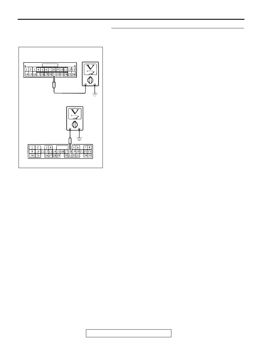
STEP 9. Check the circuit at ECM connector C-49 <2.4L-M/
T>, C-51 <3.0L-M/T>or PCM connector C-50 <2.4L-A/T>, C-
52 <3.0L-A/T>.
(1) Connect ECM connector C-49 <2.4L-M/T>, C-51 <3.0L-M/

T> or PCM connector C-50 <2.4L-A/T>, C-52 <3.0L-A/T>.

(2) Start the engine and allow it to idle.
(3) Measure the voltage between terminal number 21 <2.4L-M/

T> or 18 <2.4L-A/T, 3.0L> and ground.

Q: Is the voltage 0.7 volt or more when the radiator fan is 

operating?
YES : 
Go to Step 11.
NO :  Go to Step 10.

AC000254

CONNECTOR C-49

CONNECTOR 
C-50, C-51, C-52

<2.4L-M/T>

<2.4L-A/T, 3.0L>

AC

ENGINE COOLING DIAGNOSIS

TSB Revision

COOLING SYSTEM

14-12

STEP 10. Check the harness wire between ECM connector 
C-49 <2.4L-M/T>, C-51 <3.0L-M/T>or PCM connector C-50 
<2.4L-A/T>, C-52 <3.0L-A/T> and fan controller connector 
A-30.
NOTE: If intermediate connector C-07 is damaged, repair or 
replace it. Refer to GROUP 00E, Harness Connector 
Inspection 

P.00E-2

.

Q: Are the harness wires between ECM connector C-49 

<2.4L-M/T>, C-51 <3.0L-M/T>or PCM connector C-50 
<2.4L-A/T>, C-52 <3.0L-A/T> and fan controller 
connector A-30 damaged?
YES : 
Repair or replace them, then go to Step 12.
NO :  Go to Step 11.

AC000244

CONNECTOR: C-07

AC

AC000245 AE

CONNECTOR: 
       C-49 <2.4L-M/T>, C-50 <2.4L-A/T>
       C-51 <3.0L-M/T>, C-52 <3.0L-A/T>

ECM <M/T>
OR
PCM <A/T>

AC000270 AB

CONNECTOR: A-30

RADIATOR
FAN

ENGINE COOLING DIAGNOSIS

TSB Revision

COOLING SYSTEM

14-13

STEP 11. Check the fan control module at ECM connector 
C-49 <2.4L-M/T>, C-51 <3.0L-M/T>or PCM connector C-50 
<2.4L-A/T>, C-52 <3.0L-A/T>.
(1) Disconnect ECM connector C-49 <2.4L-M/T>, C-51 <3.0L-

M/T> or PCM connector C-50 <2.4L-A/T>, C-52 <3.0L-A/
T>.

(2) Pull out pin 21 <2.4L-M/T> or 18 <2.4L-A/T, 3.0L> to 

disconnect it.

(3) Reconnect ECM connector C-49 <2.4L-M/T>, C-51 <3.0L-

M/T> or PCM connector C-50 <2.4L-A/T>, C-52 <3.0L-A/T> 
with pin 21 <2.4L-M/T> or 18 <2.4L-A/T, 3.0L> still 
removed.

(4) Turn the ignition switch to "ON" position.

Q: Do the radiator fan motor and condenser fan motor 

operate?
YES : 
Replace the ECM <M/T> or PCM <A/T>. Then go to 

Step 12.

NO :  Replace the radiator fan motor and fan control module 

assembly.Then go to Step 12.

STEP 12. Check the symptoms.

Q: Do the radiator fan and condenser fan operate 

correctly?
YES : 
This diagnosis is complete.
NO :  Return to Step 1.

INSPECTION PROCEDURE 4: Radiator Fan and Condenser Fan do not Change Speed or Stop

NOTE: if the engine coolant temperature reaches 110

°

C (230

°

F) or higher, the radiator fan control rotates the 

radiator fan for up to 5 minutes even after the ignition switch is turned to the "LOCK (OFF)" position [the fan 
stops its rotation when the engine coolant temperature decreases to 110

°

C (230

°

F) or lower.]

Radiator Fan and Condenser Fan Drive Circuit
Refer to 

P.14-6

.

CIRCUIT OPERATION

The fan controller is powered from fusible link 
number 5.

The ECM <M/T> or PCM <A/T> judges the 
required revolution speed of radiator fan motor 
and condenser fan motor using the input signals 
transmitted from A/C switch, automatic 
compressor controller, vehicle speed sensor and 
engine coolant temperature sensor. The ECM 
<M/T> or PCM <A/T> activates the fan controller 
to drive the radiator fan motor and condenser fan 
motor.

TECHNICAL DESCRIPTION
The fan controller has variable control of the radiator 
fan motor and the condenser fan motor speeds using 
signals transmitted from the ECM <M/T> or PCM <A/
T>.

TROUBLESHOOTING HINTS

Malfunction of fan control relay

Malfunction of fan controller

Malfunction of ECM <M/T> or PCM <A/T>

DIAGNOSIS

Required Special Tool:
MB991223: Harness Set

AC000257

<2.4L-M/T>

<2.4L-A/T, 3.0L>

CONNECTOR C-49

CONNECTOR C-50, C-51, C-52

AC

ENGINE COOLING DIAGNOSIS

TSB Revision

COOLING SYSTEM

14-14

STEP 1. Check the fan control relay.
Refer to 

P.14-18

.

Q: Is the fan control relay in good condition?

YES : Go to Step 2.
NO :  Replace the part, then go to Step 6.

STEP 2. Check the harness wire between fan control relay 
connector A-13X and fan controller connector A-30.
Q: Are the harness wire between fan control relay 

connector A-13X and fan controller connector A-30 
damaged?
YES : 
Repair or replace the part, then go to Step 6.
NO :  Go to Step 3.

STEP 3. Check the circuit at ECM connector C-49 <2.4L-M/
T>, C-51 <3.0L-M/T>or PCM connector C-50 <2.4L-A/T>, C-
52 <3.0L-A/T>.
(1) Connect ECM connector C-49 <2.4L-M/T>, C-51 <3.0L-M/

T> or PCM connector C-50 <2.4L-A/T>, C-52 <3.0L-A/T>.

(2) Start the engine and run it at idle. [Engine coolant 

temperature: 80

°

C (176

°

F) or less]

(3) Measure the voltage between terminal number 21 <2.4L-M/

T> or 18 <2.4L-A/T, 3.0L> and ground.

Q: Is the voltage 0 

 0.3 volt when radiator fan is not 

operating?
YES : 
Go to Step 6.
NO :  Go to Step 4.

AC000248AB

CONNECTOR: A-13X

BATTERY

AC000270 AB

CONNECTOR: A-30

RADIATOR
FAN

AC000257

<2.4L-M/T>

<2.4L-A/T, 3.0L>

CONNECTOR C-49

CONNECTOR C-50, C-51, C-52

AC


Content   ..  343  344  345  346   ..