Mitsubishi Eclipse / Eclipse Spyder (2000-2002). Service and repair manual - part 263


  Index      Mitsubishi     Mitsubishi Eclipse / Eclipse Spyder (2000-2002). Service and repair manual


Search            


Content   ..  261  262  263  264   ..


Mitsubishi Eclipse / Eclipse Spyder (2000-2002). Service and repair manual - part 263


MULTIPORT FUEL INJECTION (MFI) DIAGNOSIS

TSB Revision

MULTIPORT FUEL INJECTION (MFI) <3.0L ENGINE>

13B-251

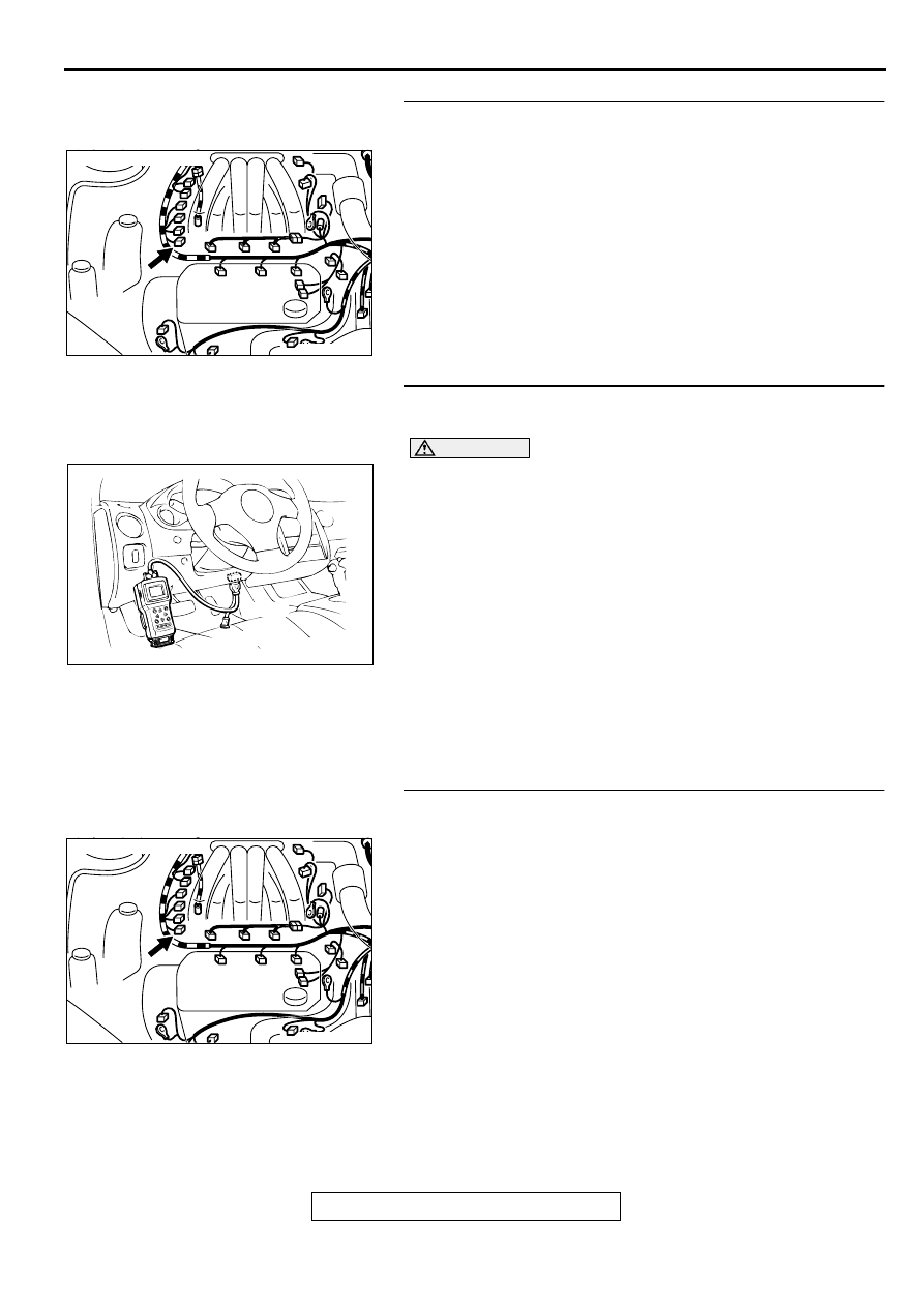
STEP 3. Check connector B-20 at the crankshaft position 
sensor for damage.
Q: Is the connector in good condition?

YES : Go to Step 4.
NO :  Repair or replace it. Refer to GROUP 00E, Harness 

Connector Inspection (

P.00E-2

). Then go to Step 20.

STEP 4. Using scan tool MB991502, check data list item 22: 
Crankshaft Position Sensor.

CAUTION

To prevent damage to scan tool MB991502, always turn the 
ignition switch to the "LOCK" (OFF) position before 
connecting or disconnecting scan tool MB991502.
(1) Connect scan tool MB991502 to the data link connector.
(2) Turn the ignition switch to the "ON" position.
(3) Set scan tool MB991502 to the data reading mode for item 

22, Crankshaft Position Sensor.

The tachometer and engine speed indicated on the scan 
tool should much.

(4) Turn the ignition switch to the "LOCK" (OFF) position.

Q: Is the sensor operating properly?

YES : It can be assumed that this malfunction is intermittent. 

Refer to GROUP 00, How to Use Troubleshooting/
Inspection Service Points (

P.00-6

).

NO :  Replace the ECM or PCM. Then go to Step 20.

STEP 5. Check connector B-20 at the crankshaft position 
sensor for damage.
Q: Is the connector in good condition?

YES : Go to Step 6.
NO :  Repair or replace it. Refer to GROUP 00E, Harness 

Connector Inspection (

P.00E-2

). Then go to Step 20.

AK000216AB

AK000216

CONNECTOR : B-20

AKX01177

16 PIN

MB991502

AB

AK000216AB

AK000216

CONNECTOR : B-20

MULTIPORT FUEL INJECTION (MFI) DIAGNOSIS

TSB Revision

MULTIPORT FUEL INJECTION (MFI) <3.0L ENGINE>

13B-252

STEP 6. Check the sensor supply voltage at crankshaft 
position sensor harness side connector B-20.
(1) Disconnect the connector B-20 and measure at the harness 

side.

(2) Turn the ignition switch to the "ON" position.
(3) Measure the voltage between terminal 2 and ground.

Voltage should be between 4.8 and 5.2 volts

(4) Turn the ignition switch to the "LOCK" (OFF) position.

Q: Is the voltage normal?

YES : Go to Step 11.
NO :  Go to Step 7.

STEP 7. Check the sensor supply voltage at ECM 
connector C-58 <M/T> or PCM connector C-55 <A/T> by 
backprobing
(1) Do not disconnect the ECM connector C-58 <M/T> or PCM 

connector C-55 <A/T>.

(2) Disconnect the crankshaft position sensor connector B-20.
(3) Turn the ignition switch to the "ON" position.
(4) Measure the voltage between terminal 43 <M/T> or 45 <A/

T> and ground by backprobing.

Voltage should be between 4.8 and 5.2 volts.

(5) Turn the ignition switch to the "LOCK" (OFF) position.

Q: Is the voltage normal?

YES : Go to Step 8.
NO :  Go to Step 9.

STEP 8. Check connector C-58 at ECM <M/T> or connector 
C-55 at PCM <A/T> for damage.
Q: Is the connector in good condition?

YES : Repair it because of open circuit between crankshaft 

position sensor connector B-20 terminal 2 and ECM 
connector C-58 terminal 43 <M/T> or PCM connector 
C-55 terminal 45 <A/T>. Then go to Step 20.

NO :  Repair or replace it. Refer to GROUP 00E, Harness 

Connector Inspection (

P.00E-2

). Then go to Step 20.

AKX01416 AC

2 1

3

B-20 HARNESS
SIDE CONNECTOR

AK000248

41 42 43 44
48

50 51

49

52 53 54 55 56 57 58 59

45 46 47

60 61

62 63 64

65

67 68

66

AK000248AC

<M/T>

C-58 CONNECTOR
HARNESS SIDE VIEW

AKX01544

AKX01544

41

AE

<A/T>

C-55 CONNECTOR
HARNESS SIDE VIEW

42 43

44 45 46

47 48 49 50 51 52 53 54 55 56 57

58 59

60 61 62 63

64 65 66

AK000225

CONNECTOR : C-58<M/T>, C-55<A/T>

C-55

C-58

PCM<A/T>

ECM<M/T>

AI

MULTIPORT FUEL INJECTION (MFI) DIAGNOSIS

TSB Revision

MULTIPORT FUEL INJECTION (MFI) <3.0L ENGINE>

13B-253

STEP 9. Check connector C-58 at ECM <M/T> or connector 
C-55 at PCM <A/T> for damage.
Q: Is the connector in good condition?

YES : Go to Step 10.
NO :  Repair or replace it. Refer to GROUP 00E, Harness 

Connector Inspection (

P.00E-2

). Then go to Step 20.

STEP 10. Check for short circuit to ground between 
crankshaft position sensor connector B-20 terminal 2 and 
ECM connector C-58 terminal 43 <M/T> or PCM connector 
C-55 terminal 45 <A/T>.
Q: Is the harness wire in good condition?

YES : Replace the ECM or PCM. Then go to Step 20.
NO :  Repair it. Then go to Step 20.

AK000225

CONNECTOR : C-58<M/T>, C-55<A/T>

C-55

C-58

PCM<A/T>

ECM<M/T>

AI

AK000216AB

AK000216

CONNECTOR : B-20

AK000225

CONNECTOR : C-58<M/T>, C-55<A/T>

C-55

C-58

PCM<A/T>

ECM<M/T>

AI

MULTIPORT FUEL INJECTION (MFI) DIAGNOSIS

TSB Revision

MULTIPORT FUEL INJECTION (MFI) <3.0L ENGINE>

13B-254

STEP 11. Check the power supply voltage at crankshaft 
position sensor harness side connector B-20.
(1) Disconnect the connector B-20 and measure at the harness 

side.

(2) Turn the ignition switch to the "ON" position.
(3) Measure the voltage between terminal 3 and ground.

Voltage should be battery positive voltage.

(4) Turn the ignition switch to the "LOCK" (OFF) position.

Q: Is the voltage normal?

YES : Go to Step 13.
NO :  Go to Step 12.

STEP 12. Check connector A-21X at MFI relay for damage.
Q: Is the connector in good condition?

YES : Repair harness wire between MFI relay connector A-

21X terminal 1 and crankshaft position sensor 
connector B-20 terminal 3 because of open circuit or 
short circuit to ground. Then go to Step 20.

NO :  Repair or replace it. Refer to GROUP 00E, Harness 

Connector Inspection (

P.00E-2

). Then go to Step 20.

STEP 13. Check the continuity at crankshaft position 
sensor harness side connector B-20.
(1) Disconnect the connector B-20 and measure at the harness 

side.

(2) Check for the continuity between terminal 1 and ground.

Should be less than 2 ohm.

Q: Is the continuity normal?

YES : Go to Step 14.
NO :  Repair harness wire between crankshaft position 

sensor connector B-20 terminal 1 and ground 
because of open circuit or harness damage. Then go 
to Step 20.

AKX01417AC

2 1

3

B-20 HARNESS
SIDE CONNECTOR

AK000226

AK000226AB

CONNECTOR : A-21X

MFI RELAY

AKX01418 AC

2 1

3

B-20 HARNESS
SIDE CONNECTOR


Content   ..  261  262  263  264   ..