Mitsubishi Eclipse / Eclipse Spyder (2000-2002). Service and repair manual - part 245
MULTIPORT FUEL INJECTION (MFI) DIAGNOSIS
TSB Revision
MULTIPORT FUEL INJECTION (MFI) <3.0L ENGINE>
13B-179
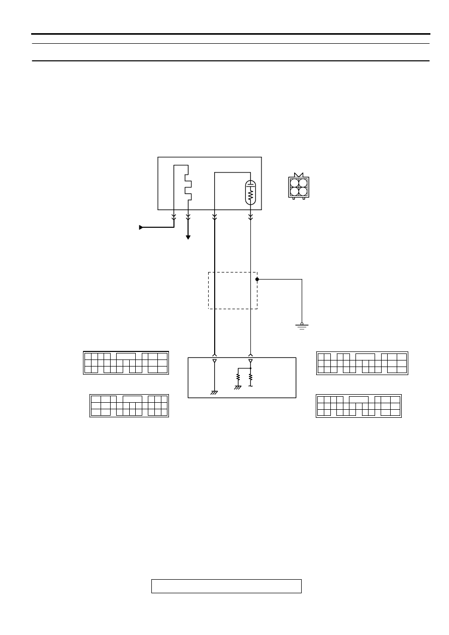
DTC P0156: O
2
Sensor Circuit Malfunction (bank 2 sensor 2)
AK000696
BLA
CK
BLA
CK
GREEN
3 4
1 2
FROM MFI RELAY
LEFT BANK HEATED
OXYGEN SENSOR(REAR)
TO ECM
OR PCM
73<M/T>*2
73<A/T>*4
49<M/T>*1
57<A/T>*3
1
3
2
4
B-23
MU802665
NOTE
*1:ECM connector C-58<M/T>
*2:ECM connector C-62<M/T>
*3:PCM connector C-55<A/T>
*4:PCM connector C-59<A/T>
ENGINE CONTROL
MODULE(ECM)<M/T>
OR
POWERTRAIN CONTROL
MODULE(PCM)<A/T>
65
43
50
42
49
41
48
60 61
64
46 47
58 59
67 68
45
56
66
52
51
44
53
62
54
63
57
55
C-58<M/T>
(MU803782)
C-55<A/T>
(MU803781)
42 43
48 49 50 51 52 53 54 55 56 57
46
45
44
58 59
60 61 62 63
64 65 66
47
41
98
78
71
88 89
76 77
72
79
91
73
80
74
75
81
92
82 83
93
84 85
94
86 87
95 96
90
80
87
81
94
85
82
84
93
86
98
99
74
92
73
83
88
91
95
97
96
100
89
78
71
90
76 77
75
72
79
97
C-62<M/T>
(MU803783)
C-59<A/T>
(MU803782)