Mitsubishi Eclipse / Eclipse Spyder (2000-2002). Service and repair manual - part 242


  Index      Mitsubishi     Mitsubishi Eclipse / Eclipse Spyder (2000-2002). Service and repair manual


Search            


Content   ..  240  241  242  243   ..


Mitsubishi Eclipse / Eclipse Spyder (2000-2002). Service and repair manual - part 242


MULTIPORT FUEL INJECTION (MFI) DIAGNOSIS

TSB Revision

MULTIPORT FUEL INJECTION (MFI) <3.0L ENGINE>

13B-167

Under the closed loop air/fuel control.

Monitoring time: 30seconds.

Judgment Criteria

Multiport fuel injection system does not enter the 
closed loop control within about 30 seconds of 
meeting all criteria above.

TROUBLESHOOTING HINTS (The most likely 
causes for this code to be set are:)

Left bank heated oxygen sensor (front) 
deteriorated.

Open circuit in left bank heated oxygen sensor 
(front) output line.

Open circuit in left bank heated oxygen sensor 
(front) ground line.

ECM failed. <M/T>

PCM failed. <A/T>

DIAGNOSIS

Required Special Tools
MB998464: Test Harness

STEP 1. Check the exhaust leaks.

Q: Are there any abnormalities?

YES : Go to Step 2.
NO :  Repair it. Then go to Step 11.

STEP 2. Check the intake system vacuum leak.

Q: Are there any abnormalities?

YES : Go to Step 3.
NO :  Repair it. Then go to Step 11.

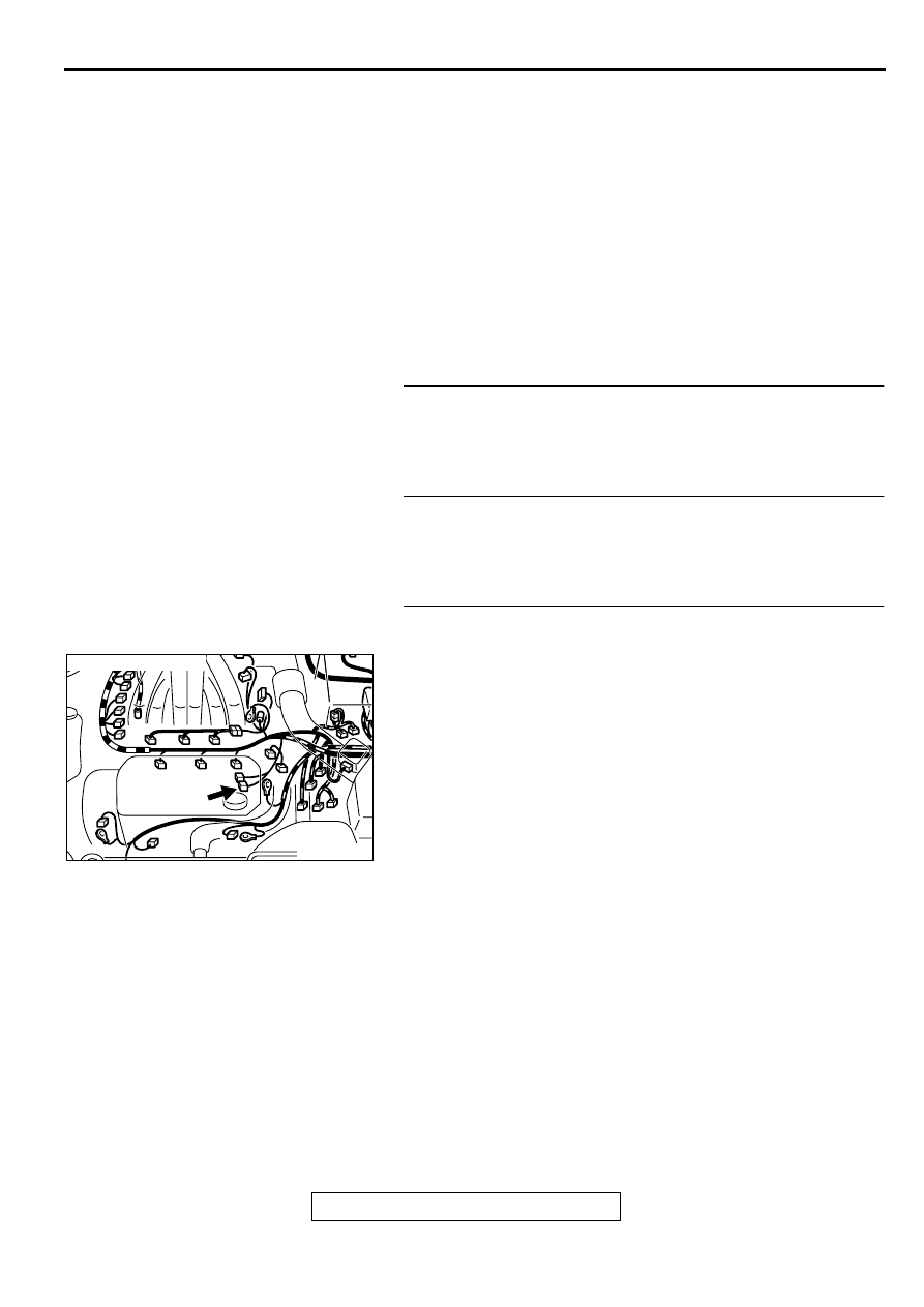
STEP 3. Check connector B-24 at the left bank heated 
oxygen sensor (front) for damage.
Q: Is the connector in good condition?

YES : Go to Step 4.
NO :  Repair or replace it. Refer to GROUP 00E, Harness 

Connector Inspection (

P.00E-2

). Then go to Step 11.

AK000212AB

AK000212

CONNECTOR : B-24

MULTIPORT FUEL INJECTION (MFI) DIAGNOSIS

TSB Revision

MULTIPORT FUEL INJECTION (MFI) <3.0L ENGINE>

13B-168

STEP 4. Check the left bank heated oxygen sensor (front).
(1) Disconnect the left bank heated oxygen sensor (front) 

connector B-24 and connect test harness special tool 
MD998464 to the connector on the left bank heated oxygen 
sensor (front) side.

(2) Warm up the engine until engine coolant 80

°

 C (176

°

 F) or 

higher.

CAUTION

Be very careful when connecting the jumper wires; 
incorrect connection can damage the left bank heated 
oxygen sensor (front).
(3) Use the jumper wires to connect terminal 1 (red clip) to the 

positive battery terminal and terminal 3 (blue clip) to the 
negative battery terminal.

(4) Connect a digital volt meter between terminal 2 (black clip) 

and terminal 4 (white clip).

(5) While repeatedly revving the engine, measure the left bank 

heated oxygen sensor (front) output voltage.

Standard value: 0.6 

 1.0 V

Q: Is the voltage at the standard value?

YES : Go to Step 5.
NO :  Replace the left bank heated oxygen sensor (front). 

Then go to Step 11.

STEP 5. Check connector B-02, B-06, B-25 at left bank 
injector for damage.
Q: Is the connector in good condition?

YES : Go to Step 6.
NO :  Repair or replace it. Refer to GROUP 00E, Harness 

Connector Inspection (

P.00E-2

). Then go to Step 11.

ACX02489AC

CONNECTOR : B-24

LEFT BANK
HEATED OXYGEN
SENSOR
(FRONT)

AKX01624

HEATED
OXYGEN
SENSOR
EQUIPMENT
SIDE
CONNECTOR

MD998464

BLUE

RED

AC

AKX01625AC

BLUE

RED

BLACK

JUMPER
WIRES

WHITE

MD998464

AK000213AB

CONNECTORS : B-02, B-06, B-25

B-02 B-06 B-25

MULTIPORT FUEL INJECTION (MFI) DIAGNOSIS

TSB Revision

MULTIPORT FUEL INJECTION (MFI) <3.0L ENGINE>

13B-169

STEP 6. Check the left bank injector.
(1) Disconnect the left bank injector connector B-02, B-06, B-

25.

(2) Measure the resistance between each injector side 

connector terminal 1 and 2.

Standard value: 13 

 16 ohm [at 20

° 

C (68

°

 F)]

Q: Is the resistance standard value?

YES : Go to Step 7.
NO :  Replace the faulty injector. Then go to Step 11.

STEP 7. Check connector C-51, C-62 at ECM <M/T> or 
connector C-59, C-52 at PCM <A/T> for damage.
Q: Is the connector in good condition?

YES : Go to Step 8.
NO :  Repair or replace it. Refer to GROUP 00E, Harness 

Connector Inspection (

P.00E-2

). Then go to Step 11.

AK000213AB

CONNECTORS : B-02, B-06, B-25

B-02 B-06 B-25

AK000559

2

1

INJECTOR SIDE
CONNECTOR

AB

AK000225

CONNECTORS : C-51, C-62<M/T>,
C-52, C-59<A/T>

C-52

C-51

PCM<A/T>

ECM<M/T>

AM

C-59

C-62

MULTIPORT FUEL INJECTION (MFI) DIAGNOSIS

TSB Revision

MULTIPORT FUEL INJECTION (MFI) <3.0L ENGINE>

13B-170

STEP 8. Check for harness damage between left bank 
heated oxygen sensor (front) connector B-24 terminal 4 
and ECM connector C-62 terminal 71 <M/T> or PCM 
connector C-59 terminal 71 <A/T>.
Q: Is the harness wire in good condition?

YES : Go to Step 9.
NO :  Repair it. Then go to Step 11.

STEP 9. Check for harness damage between left bank 
injector connector and ECM connector <M/T> or PCM 
connector <A/T>.

a. Check the harness wire between injector connector B-02 

terminal 2 and ECM connector C-51 terminal 9 <M/T> or 
PCM connector C-52 terminal 9 <A/T> when checking No.2 
cylinder.

b. Check the harness wire between injector connector B-06 

terminal 2 and ECM connector C-51 terminal 2 <M/T> or 
PCM connector C-52 terminal 2 <A/T> when checking No.4 
cylinder.

c. Check the harness wire between injector connector B-25 

terminal 2 and ECM connector C-51 terminal 25 <M/T> or 
PCM connector C-52 terminal 25 <A/T> when checking 
No.6 cylinder.

Q: Is the harness wire in good condition?

YES : Go to Step 10.
NO :  Repair it. Then go to Step 11.

AK000212AB

AK000212

CONNECTOR : B-24

AK000225

CONNECTOR : C-62<M/T>, C-59<A/T>

C-59

C-62

PCM<A/T>

ECM<M/T>

AL

AK000213AB

CONNECTORS : B-02, B-06, B-25

B-02 B-06 B-25

AK000225

CONNECTOR : C-51<M/T>, C-52<A/T>

C-52

C-51

PCM<A/T>

ECM<M/T>

AJ


Content   ..  240  241  242  243   ..