Mitsubishi Eclipse / Eclipse Spyder (2000-2002). Service and repair manual - part 234


  Index      Mitsubishi     Mitsubishi Eclipse / Eclipse Spyder (2000-2002). Service and repair manual


Search            


Content   ..  232  233  234  235   ..


Mitsubishi Eclipse / Eclipse Spyder (2000-2002). Service and repair manual - part 234


MULTIPORT FUEL INJECTION (MFI) DIAGNOSIS

TSB Revision

MULTIPORT FUEL INJECTION (MFI) <3.0L ENGINE>

13B-135

CIRCUIT OPERATION

A voltage corresponding to the oxygen 
concentration in the exhaust gas is sent to the 
ECM (terminal 74) <M/T> or PCM (terminal 74) 
<A/T> from the output terminal (terminal 4) of the 
right bank heated oxygen sensor (rear).

Terminal 2 of the right bank heated oxygen 
sensor (rear) is grounded with ECM (terminal 49) 
<M/T> or PCM (terminal 57) <A/T>.

TECHNICAL DESCRIPTION

The output signal of the right bank heated oxygen 
sensor (front) is compensated by the output 
signal of the right bank heated oxygen sensor 
(rear).

The ECM <M/T> or PCM <A/T> checks for an 
open circuit in the right bank heated oxygen 
sensor (rear) output line.

DTC SET CONDITIONS

Check Conditions

Right bank heated oxygen sensor (rear) signal 
voltage has continued to be 0.15 volt or lower for 
three minutes or more after the starting sequence 
was completed.

Engine coolant temperature is higher than 82

°

 C 

(180

°

 F).

Engine speed is higher than 1,200 r/min.

Volumetric efficiency is higher than 25 percent.

Monitoring time: 7 seconds.

Judgment Criteria

Input voltage supplied to the ECM <M/T> or PCM 
<A/T> interface circuit is higher than 4.5 volts 
when 5 volts is applied to the right bank heated 
oxygen sensor (rear) output line via a resistor.

Only one monitor during one drive cycle

Check Conditions

Right bank heated oxygen sensor (rear) signal 
voltage has continued to be 0.15 volt or lower for 
three minutes or more after the starting sequence 
was completed.

Engine coolant temperature is higher than 82

°

 C 

(180

°

 F).

Engine speed is higher than 1,200 r/min.

Volumetric efficiency is higher than 25 percent.

Volume air flow sensor output frequency is 75 Hz 
or more.

At least twenty seconds have passed since fuel 
shut off control was canceled.

The right bank heated oxygen sensor (front) 
outputs 0.5 volts or more.

Monitoring time: 10 seconds

Judgement Criteria

Making the air/fuel ratio 15 percent for 10 
seconds richer does not result in raising the right 
bank heated oxygen sensor (rear) output voltage 
beyond 0.15 volt.

Only one monitor during one drive cycle

TROUBLESHOOTING HINTS (The most likely 
causes for this code to be set are:)

Right bank heated oxygen sensor (rear) failed.

Open circuit in right bank heated oxygen sensor 
(rear) output line.

Open circuit in right bank heated oxygen sensor 
(rear) ground line.

ECM failed. <M/T>

PCM failed. <A/T>

DIAGNOSIS

Required Special Tools
MB991502: Scan Tool (MUT-II)
MB991316: Test Harness
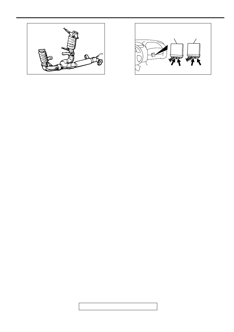
ACX02493AC

CONNECTOR : B-28

RIGHT BANK
HEATED OXYGEN
SENSOR(REAR)

AK000225

CONNECTORS : C-58, C-62<M/T>,
C-55, C-59<A/T>

C-55

C-58

PCM<A/T>

ECM<M/T>

AK

C-59

C-62

MULTIPORT FUEL INJECTION (MFI) DIAGNOSIS

TSB Revision

MULTIPORT FUEL INJECTION (MFI) <3.0L ENGINE>

13B-136

STEP 1. Using scan tool MB991502, check data list item 69: 
Heated Oxygen Sensor Bank 1, Sensor 2 (right rear).

CAUTION

To prevent damage to scan tool MB991502, always turn the 
ignition switch to the "LOCK" (OFF) position before 
connecting or disconnecting scan tool MB991502.
(1) Connect scan tool MB991502 to the data link connector.
(2) Start the engine and run at idle.
(3) Set scan tool MB991502 to the data reading mode for item 

69, Heated Oxygen Sensor Bank 1, Sensor 2 (right rear).

Warming up the engine. When the engine is revved, the 
output voltage should repeat 0 volt and 0.6 to 1.0 volt 
alternately.

(4) Turn the ignition switch to the "LOCK" (OFF) position.

Q: Is the sensor operating properly?

YES : It can be assumed that this malfunction is intermittent. 

Refer to GROUP 00, How to Use Troubleshooting/
Inspection Service Points (

P.00-6

).

NO :  Go to Step 2.

STEP 2. Check the sensor output voltage at right bank 
heated oxygen sensor (rear) connector B-28 by 
backprobing.
(1) Do not disconnect the connector B-28.
(2) Start the engine and run at idle.
(3) Measure the voltage between terminal 4 and ground by 

backprobing.

Warming up the engine. When the engine is revved, the 
output voltage should repeat 0 volt and 0.6 to 1.0 volt 
alternately.

(4) Turn the ignition switch to the "LOCK" (OFF) position.

Q: Is the voltage normal?

YES : Go to Step 3.
NO :  Go to Step 7.

AKX01177

16 PIN

MB991502

AB

AKX01538

1 2
3 4

AD

B-28 CONNECTOR
HARNESS
SIDE VIEW

MULTIPORT FUEL INJECTION (MFI) DIAGNOSIS

TSB Revision

MULTIPORT FUEL INJECTION (MFI) <3.0L ENGINE>

13B-137

STEP 3. Check the sensor output voltage at ECM 
connector C-62 <M/T> or PCM connector C-59 <A/T> by 
backprobing.
(1) Do not disconnect the connector C-62 <M/T> or C-59 <A/

T>.

(2) Start the engine and run at idle.
(3) Measure the voltage between terminal 74 and ground by 

backprobing.

Warming up the engine. When the engine is 2,500 r/min, 
the output voltage should repeat 0 volt and 0.6 to 1.0 
volt alternately.

(4) Turn the ignition switch to the "LOCK" (OFF) position.

Q: Is the voltage normal?

YES : Go to Step 4.
NO :  Go to Step 6.

STEP 4. Check connector B-28 at right bank heated 
oxygen sensor (rear) and connector C-62 at ECM <M/T> or 
connector C-59 at PCM <A/T> for damage.
Q: Is the connector in good condition?

YES : Go to Step 5.
NO :  Repair or replace it. Refer to GROUP 00E, Harness 

Connector Inspection (

P.00E-2

). Then go to Step 15.

AK000242

71 72

73 74

78

80 81

79

82 83 84 85 86 87 88 89

75 76

91 92 93

94 95

96

98

99

97

AK000242AC

<M/T>

C-62 CONNECTOR
HARNESS SIDE VIEW

77

90

100

AKX01536

7172 73 74

75 76 77

78 79 80 81 82 83 84 85 86 87 88 89
90 91

92 93 94

95 96

97 98

C-59 CONNECTOR
HARNESS SIDE VIEW

AF

<A/T>

AK000211

CONNECTOR : B-28

AB

AK000225

CONNECTOR : C-62<M/T>, C-59<A/T>

C-59

C-62

PCM<A/T>

ECM<M/T>

AL

MULTIPORT FUEL INJECTION (MFI) DIAGNOSIS

TSB Revision

MULTIPORT FUEL INJECTION (MFI) <3.0L ENGINE>

13B-138

STEP 5. Using scan tool MB991502, check data list item 69: 
Heated Oxygen Sensor Bank 1, Sensor 2 (right rear).

CAUTION

To prevent damage to scan tool MB991502, always turn the 
ignition switch to the "LOCK" (OFF) position before 
connecting or disconnecting scan tool MB991502.
(1) Connect scan tool MB991502 to the data link connector.
(2) Start the engine and run at idle.
(3) Set scan tool MB991502 to the data reading mode for item 

69, Heated Oxygen Sensor Bank 1, Sensor 2 (right rear).

Warming up the engine. When the engine is revved, the 
output voltage should repeat 0 volt and 0.6 to 1.0 volt 
alternately.

(4) Turn the ignition switch to the "LOCK" (OFF) position.

Q: Is the sensor operating properly?

YES : It can be assumed that this malfunction is intermittent. 

Refer to GROUP 00, How to Use Troubleshooting/
Inspection Service Points (

P.00-6

).

NO :  Replace the ECM or PCM. Then go to Step 15.

STEP 6. Check connector B-28 at right bank heated 
oxygen sensor (rear) and connector C-62 at ECM <M/T> or 
connector C-59 at PCM <A/T> for damage.
Q: Is the connector in good condition?

YES : Repair harness wire between right bank heated 

oxygen sensor (rear) connector B-28 terminal 4 and 
ECM connector C-62 terminal 74 <M/T> or PCM 
connector C-59 terminal 74 <A/T> because of open 
circuit or harness damage. Then go to Step 15.

NO :  Repair or replace it. Refer to GROUP 00E, Harness 

Connector Inspection (

P.00E-2

). Then go to Step 15.

AKX01177

16 PIN

MB991502

AB

AK000211

CONNECTOR : B-28

AB

AK000225

CONNECTOR : C-62<M/T>, C-59<A/T>

C-59

C-62

PCM<A/T>

ECM<M/T>

AL


Content   ..  232  233  234  235   ..