Mitsubishi Eclipse / Eclipse Spyder (2000-2002). Service and repair manual - part 201
GENERAL INFORMATION
TSB Revision
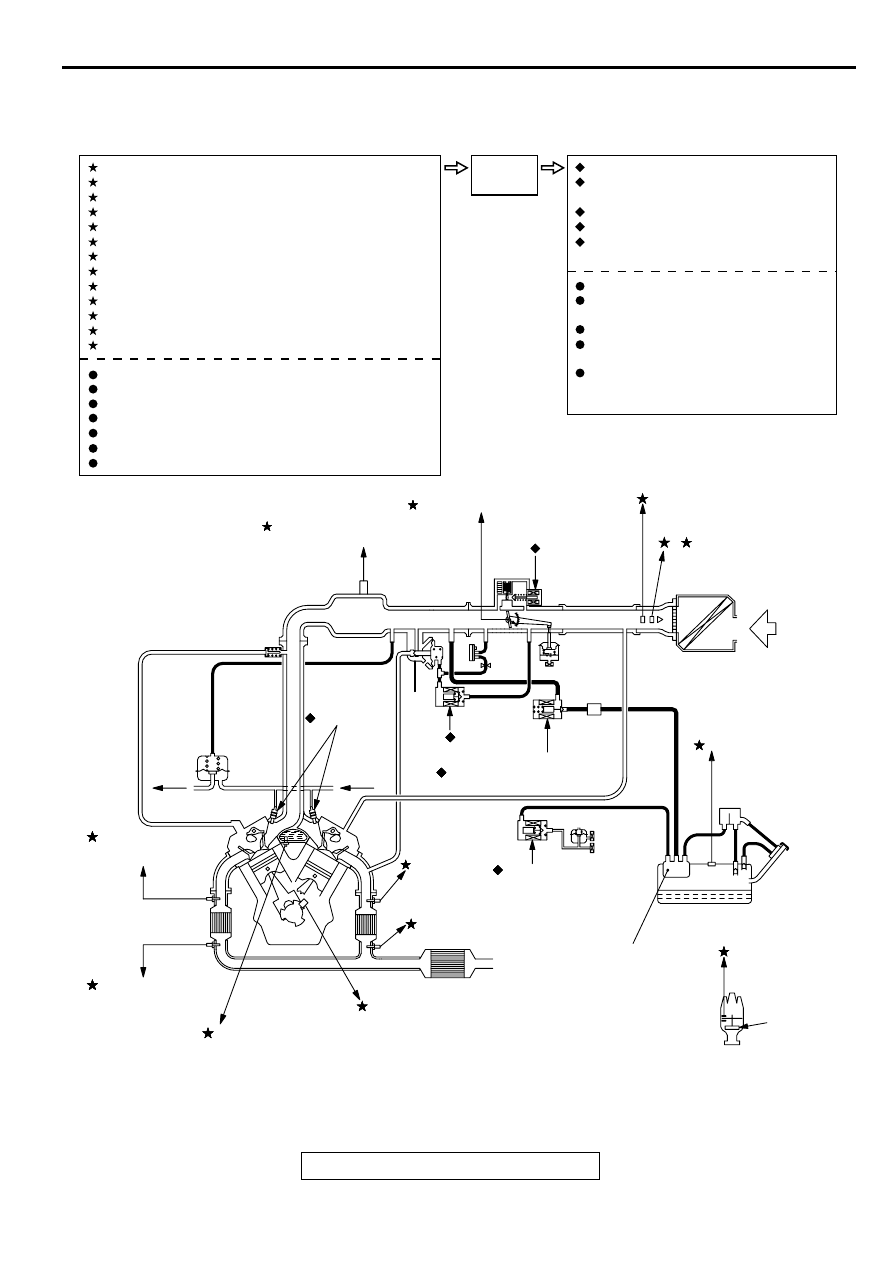
MULTIPORT FUEL INJECTION (MFI) <3.0L ENGINE>
13B-3
MULTIPORT FUEL INJECTION (MFI) SYSTEM DIAGRAM
NOTE: For the vacuum hose routing, refer to
GROUP 17, vacuum hoses
.
AK000045
CATALYTIC CONVERTER
FUEL PRESSURE
REGULATOR
M*1
*2
M*1
EGR
VALVE
DASH
POT
<M/T>
FROM
FUEL
PUMP
TO
FUEL
TANK
1 LEFT BANK HEATED OXYGEN SENSOR (FRONT)
2 VOLUME AIR FLOW SENSOR
3 INTAKE AIR TEMPERATURE SENSOR
4 THROTTLE POSITION SENSOR
5 CAMSHAFT POSITION SENSOR
6 CRANKSHAFT POSITION SENSOR
7 BAROMETRIC PRESSURE SENSOR
8 ENGINE COOLANT TEMPERATURE SENSOR
9 LEFT BANK HEATED OXYGEN SENSOR (REAR)
10 RIGHT BANK HEATED OXYGEN SENSOR (FRONT)
11 RIGHT BANK HEATED OXYGEN SENSOR (REAR)
12 MANIFOLD DIFFERENTIAL PRESSURE SENSOR
13 FUEL TANK DIFFERENTIAL PRESSURE SENSOR
POWER SUPPLY
VEHICLE SPEED SENSOR
A/C SWITCH
PARK/NEUTRAL POSITION SWITCH <A/T>
POWER STEERING PRESSURE SWITCH
IGNITION SWITCH - ST
KNOCK SENSOR
1 INJECTOR
2 EVAPORATIVE EMISSION
PURGE SOLENOID
3 IDLE AIR CONTROL MOTOR
4 EGR SOLENOID
5 EVAPORATIVE EMISSION
VENTILATION SOLENOID
FUEL PUMP RELAY
MULTIPORT FUEL INJECTION
(MFI) RELAY
A/C COMPRESSER CLUTCH RELAY
SERVICE ENGINE SOON/
MALFUNCTION INDICATOR LAMP
DIAGNOSTIC OUTPUT
ECM<M/T>
PCM<A/T>
SENSE
DECIDE
ACT
AB
NOTE
*1 : Manifold port
*2 : Restrictor
3 INTAKE AIR
TEMPERATURE SENSOR
2, 7
VOLUME AIR FLOW SENSOR
(WITH BAROMETRIC
PRESSURE SENSOR)
3 IDLE AIR
CONTROL
MOTOR
4 THROTTLE POSITION SENSOR
12 MANIFOLD DIFFERENTIAL
PRESSURE SENSOR
1 INJECTOR
E
CHAMBER
VCV
A
EGR
5 SOLENOID
EVAPORATIVE EMISSION
2 PURGE SOLENOID
8 ENGINE
COOLANT
TEMPERATURE
SENSOR
10 RIGHT BANK
HEATED OXYGEN
SENSOR (FRONT)
11 RIGHT BANK
HEATED OXYGEN
SENSOR (REAR)
CRANKSHAFT POSITION
SENSOR
6
9 LEFT BANK HEATED
OXYGEN SENSOR (REAR)
5 CAMSHAFT
POSITION
SENSOR
13 FUEL TANK
DIFFERENTIAL
PRESSURE SENSOR
LEFT BANK
HEATED
1 OXYGEN
SENSOR
(FRONT)
EVAPORATIVE
EMISSION
CANISTER
4 EVAPORATIVE
EMISSION
VENTILATION
SOLENOID
FUEL TANK
AIR INLET
DISTRIBUTOR
IGNITION
COIL
VENT VALVE