Mitsubishi Eclipse / Eclipse Spyder (2000-2002). Service and repair manual - part 178


  Index      Mitsubishi     Mitsubishi Eclipse / Eclipse Spyder (2000-2002). Service and repair manual


Search            


Content   ..  176  177  178  179   ..


Mitsubishi Eclipse / Eclipse Spyder (2000-2002). Service and repair manual - part 178


MULTIPORT FUEL INJECTION (MFI) DIAGNOSIS

TSB Revision

MULTIPORT FUEL INJECTION (MFI) <2.4L ENGINE>

13A-411

The ECM (terminal 13, 26) <M/T> or PCM 
(terminals 42, 48) <A/T> is grounded to the 
vehicle body.

TROUBLESHOOTING HINTS (The most likely 
causes for this code to be set are:) 

Malfunction of the ignition switch.

Malfunction of the MFI relay.

Improper connector contact, open circuit or short-
circuited harness wire.

Disconnected ECM <M/T> or PCM <A/T> ground 
wire.

Malfunction of the ECM <M/T> or PCM <A/T>.

DIAGNOSIS

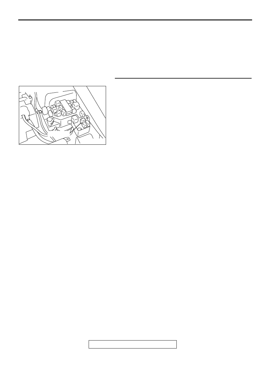
STEP 1. Check connector A-21X at MFI relay for damage.
Q: Is the connector in good condition?

YES :  Go to Step 2.
NO :  Repair or replace it. Refer to GROUP 00E, Harness 

Connector Inspection (

P.00E-2

). Then confirm that 

the malfunction symptom is eliminated.

AK000226

AK000226AB

CONNECTOR : A-21X

MFI RELAY

MULTIPORT FUEL INJECTION (MFI) DIAGNOSIS

TSB Revision

MULTIPORT FUEL INJECTION (MFI) <2.4L ENGINE>

13A-412

STEP 2. Check the MFI relay
(1) Remove the MFI relay.
(2) Check for continuity between the MFI relay terminals 2 and 

4.

There should be continuity (approximately 70

)

(3) Use jumper wires to connect MFI relay terminal 4 to the 

positive   battery terminal and terminal 2 to the negative 
battery terminal.

(4) Check the continuity between the MFI relay terminals 1 and 

3   while connecting and disconnecting the jumper wire at 
the negative battery terminal.

Should be less than 2 ohm. (Negative battery terminal 
connected)

Should be open loop. (Negative battery terminal 
disconnected)

(5)  Install the MFI relay.

Q: Is the voltage normal?

YES : Go to Step 3.
NO :  Replace the MFI relay. Then confirm that the 

malfunction symptom is eliminated.

STEP 3. Check the power supply voltage at MFI relay 
harness side connector A-21X.
(1) Disconnect the connector A-21X and measure at the 

harness side.

(2) Measure the voltage between terminal 3, 4 and ground.

Voltage should be battery positive voltage.

Q: Is the voltage normal?

YES : Go to Step 4.
NO :  Check harness connector C-07 at intermediate 

connector for damage, and repair or replace as 
required. Refer to, GROUP 00E, Harness Connector 
Inspection (

P.00E-2

). If intermediate connector is in 

good condition, repair harness wire between fusible 
link (13) and MFI relay connector A-21X terminal 3, 4 
because of open circuit. Then confirm that the 
malfunction symptom is eliminated.

AK000226

AK000226AB

CONNECTOR : A-21X

MFI RELAY

AK000369AB

MFI RELAY SIDE
CONNECTOR

1 2
3 4

AK000370AB

MFI RELAY SIDE
CONNECTOR

1 2
3 4

AK000371AB

1

2

3

4

A-21X HARNESS
SIDE CONNECTOR

MULTIPORT FUEL INJECTION (MFI) DIAGNOSIS

TSB Revision

MULTIPORT FUEL INJECTION (MFI) <2.4L ENGINE>

13A-413

STEP 4. Check connector C-60 at ECM <M/T> or connector 
C-57 at PCM <A/T> for damage.
Q: Is the connector in good condition?

YES : Go to Step 5.
NO :  Repair or replace it. Refer to GROUP 00E, Harness 

Connector Inspection (

P.00E-2

). Then confirm that 

the malfunction symptom is eliminated.

STEP 5. Check the ignition switch-IG signal voltage at ECM 
harness side connector C-60 <M/T> or PCM harness side 
connector C-57 <A/T>.
(1) Disconnect the connector C-60 <M/T> or C-57 <A/T> and 

measure at the harness side.

(2) Turn the ignition switch to the "ON" position.
(3) Measure the voltage between terminal 82 <M/T> or 98 <A/

T> and ground.

Voltage should be battery positive voltage.

(4) Turn the ignition switch to the "LOCK" (OFF) position.

Q: Is the voltage normal?

YES : Go to Step 6.
NO :  Check harness connector C-07, C-89 and C-101 at 

intermediate connector for damage, and repair or 
replace as required. Refer to, GROUP 00E, Harness 
Connector Inspection (

P.00E-2

). If intermediate 

connectors are in good condition, repair harness wire 
between ignition switch connector C-87 terminal 2 
and ECM connector C-60 terminal 82 <M/T> or PCM 
connector C-57 terminal 98 <A/T> because of open 
circuit. Then confirm that the malfunction symptom is 
eliminated.

AK000280

C-60

ECM<M/T>
OR
PCM<A/T>

CONNECTORS:C-60<M/T>,C-57<A/T>

BE

C-57

AK000402 AC

71

72

73

74

75

76

77

78

79

80

81

82

83

84

85

86

87

88

89

90

91

92

<M/T>

C-60 HARNESS
SIDE CONNECTOR

AKX01435

77 76
89 88
98

75
87

97

86
96

85
95

84

82

83
94 93

81
92

80

74 73 72 71

79 78
91 90

AF

<A/T>
      C-57  HARNESS
      SIDE  CONNECTOR

MULTIPORT FUEL INJECTION (MFI) DIAGNOSIS

TSB Revision

MULTIPORT FUEL INJECTION (MFI) <2.4L ENGINE>

13A-414

STEP 6. Check the backup power supply voltage at ECM 
harness side connector C-60 <M/T> or PCM harness side 
connector C-54 <A/T>.
(1) Disconnect the connector C-60 <M/T> or C-54 <A/T> and 

measure at the harness side.

(2) Measure the voltage between terminal 80 <M/T> or 66 <A/

T> and ground.

Voltage should be battery positive voltage.

Q: Is the voltage normal?

YES : Go to Step 7.
NO :  Check harness connector C-28, C-78 and C-89 at 

intermediate connector for damage, and repair or 
replace as required. Refer to, GROUP 00E, Harness 
Connector Inspection (

P.00E-2

). If intermediate 

connectors are in good condition, repair harness wire 
between fusible link (4) and ECM connector C-60 
terminal 80 <M/T> or PCM connector C-54 terminal 
66 <A/T> because of open circuit. Then confirm that 
the malfunction symptom is eliminated.

STEP 7. Check the continuity at ECM harness side 
connector C-49 <M/T> or PCM harness side connector C-
54 <A/T>.
(1) Disconnect the connector C-49 <M/T> or C-54 <A/T> and 

measure at the harness side.

(2) Check for the continuity between terminal (13, 26) <M/T> or 

(42, 48) <A/T> and ground.

Should be less than 2 ohm.

Q: Is the continuity normal?

YES : Go to Step 8.
NO :  Repair harness wire between ECM connector C-49 

terminal (13, 26) <M/T> or PCM connector C-54 
terminal (42, 48) <A/T> and ground because of open 
circuit. Then confirm that the malfunction symptom is 
eliminated.

AK000403 AC

71

72

73

74

75

76

77

78

79

80

81

82

83

84

85

86

87

88

89

90

91

92

<M/T>

C-60 HARNESS
SIDE CONNECTOR

AKX01436

46 45 44
57 56 55
66 65 64

54 53 52 51 50 49 48 47

43 42 41

63 62 61 60

59 58

C-54  HARNESS
SIDE  CONNECTOR

<A/T>

AF

AK000404AC

1

2

3

4

5

6

7

8

9

10

11

12

13

14

15

16

17

18

19

20

21

22

23

24

25

26

<M/T>

C-49 HARNESS
SIDE CONNECTOR

AKX01437

C-54  HARNESS
SIDE  CONNECTOR

<A/T>

46 45 44
57 56 55
66 65 64

54 53 52 51 50 49 48 47

43 42 41

63 62 61 60

59 58

AG


Content   ..  176  177  178  179   ..