Mitsubishi Eclipse / Eclipse Spyder (2000-2002). Service and repair manual - part 154
MULTIPORT FUEL INJECTION (MFI) DIAGNOSIS
TSB Revision
MULTIPORT FUEL INJECTION (MFI) <2.4L ENGINE>
13A-315
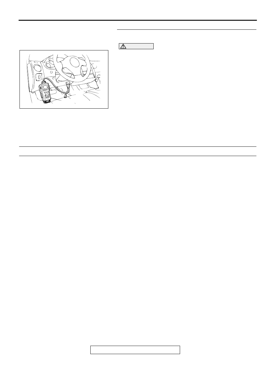
STEP 1. Using scan tool MB991502, read the A/T
diagnostic trouble code (DTC).
CAUTION
To prevent damage to scan tool MB991502, always turn the
ignition switch to the "LOCK" (OFF) position before
connecting or disconnecting scan tool MB991502.
(1) Connect scan tool MB991502 to the data link connector.
(2) Turn the ignition switch to the "ON" position.
(3) Check the A/T-DTC.
(4) Turn the ignition switch to the "LOCK" (OFF) position.
Q: Is the A/T-DTC is output?
YES : Refer to GROUP 23A, Automatic Transaxle
Diagnosis
−
Diagnostic Trouble Code Chart (
NO : If DTC P0710 is output again after the MFI-DTC has
been erased, replace the PCM. Then check that the
DTC P0710 does not reset.
DTC P0715: Input/Turbine Speed Sensor Circuit Malfunction
TECHNICAL DESCRIPTION
•
When a malfunction of the input shaft speed
sensor is detected, the transaxle control CPU
inside the powertrain control module (PCM)
outputs a malfunction signal to the engine control
CPU in the PCM.
DTC SET CONDITIONS
Check Conditions, Judgment Criteria
•
Input shaft speed sensor failure signal is input to
the engine control CPU from the transaxle control
CPU. Both CPUs are in the PCM.
TROUBLESHOOTING HINTS (The most likely
causes for this code to be set are:)
•
Input shaft speed sensor failed.
•
Open or shorted input shaft speed sensor circuit,
or loose connector.
•
PCM failed.
DIAGNOSIS
Required Special Tools
MB991502: Scan Tool (MUT-II)
AKX01177
16 PIN
MB991502
AB