Mitsubishi Eclipse / Eclipse Spyder (2000-2002). Service and repair manual - part 153


  Index      Mitsubishi     Mitsubishi Eclipse / Eclipse Spyder (2000-2002). Service and repair manual


Search            


Content   ..  151  152  153  154   ..


Mitsubishi Eclipse / Eclipse Spyder (2000-2002). Service and repair manual - part 153


MULTIPORT FUEL INJECTION (MFI) DIAGNOSIS

TSB Revision

MULTIPORT FUEL INJECTION (MFI) <2.4L ENGINE>

13A-311

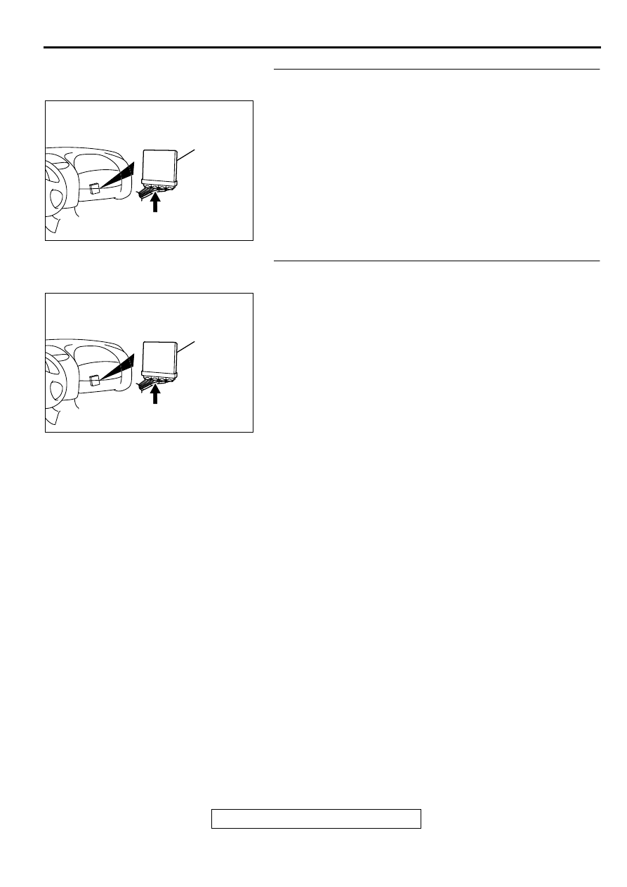
STEP 8. Check connector C-53 at ECM <M/T> or connector 
C-54 at PCM <A/T> for damage.
Q: Is the connector in good condition?

YES : Repair harness wire between power steering 

pressure switch connector B-19 terminal 1 and ECM 
connector C-53 terminal 37 <M/T> or PCM connector 
C-54 terminal 52 <A/T> because of open circuit. Then 
go to Step 14.

NO :  Repair or replace it. Refer to GROUP 00E, Harness 

Connector Inspection (

P.00E-2

). Then go to Step 14.

STEP 9. Check connector C-53 at ECM <M/T> or connector 
C-54 at PCM <A/T> for damage.
Q: Is the connector in good condition?

YES : Go to Step 10.
NO :  Repair or replace it. Refer to GROUP 00E, Harness 

Connector Inspection (

P.00E-2

). Then go to Step 14.

AK000280

C-53,C-54

ECM<M/T>
OR
PCM<A/T>

CONNECTORS:C-53<M/T>,C-54<A/T>

BH

AK000280

C-53,C-54

ECM<M/T>
OR
PCM<A/T>

CONNECTORS:C-53<M/T>,C-54<A/T>

BH

MULTIPORT FUEL INJECTION (MFI) DIAGNOSIS

TSB Revision

MULTIPORT FUEL INJECTION (MFI) <2.4L ENGINE>

13A-312

STEP 10. Check for short circuit to ground between power 
steering pressure switch connector B-19 terminal 1 and 
ECM connector C-53 terminal 37 <M/T> or PCM connector 
C-54 terminal 52 <A/T>.
Q: Is the harness wire in good condition?

YES : Replace the ECM or PCM. Then go to Step 14.
NO :  Repair it. Then go to Step 14.

STEP 11. Replace the power steering pressure switch.
(1) Replace the power steering pressure switch.
(2) Check the trouble symptoms.
(3) Check the diagnostic trouble code (DTC).

Q: Is the DTC P0551 is output?

YES : Go to Step 12.
NO :  Go to Step 14.

STEP 12. Check connector C-53 at ECM <M/T> or 
connector C-54 at PCM <A/T> for damage.
Q: Is the connector in good condition?

YES : Go to Step 13.
NO :  Repair or replace it. Refer to GROUP 00E, Harness 

Connector Inspection (

P.00E-2

). Then go to Step 14.

ACX02520

CONNECTOR : B-19

POWER STEERING
PRESSURE SWITCH

AD

AK000280

C-53,C-54

ECM<M/T>
OR
PCM<A/T>

CONNECTORS:C-53<M/T>,C-54<A/T>

BH

ACX02520

CONNECTOR : B-19

POWER STEERING
PRESSURE SWITCH

AD

AK000280

C-53,C-54

ECM<M/T>
OR
PCM<A/T>

CONNECTORS:C-53<M/T>,C-54<A/T>

BH

MULTIPORT FUEL INJECTION (MFI) DIAGNOSIS

TSB Revision

MULTIPORT FUEL INJECTION (MFI) <2.4L ENGINE>

13A-313

STEP 13. Check for harness damage between power 
steering pressure switch connector B-19 terminal 1 and 
ECM connector C-53 terminal 37 <M/T> or PCM connector 
C-54 terminal 52 <A/T>.
Q: Is the harness wire in good condition?

YES : Replace the ECM or PCM. Then go to Step 14.
NO :  Repair it. Then go to Step 14.

STEP 14. Using scan tool MB991502, check data list item 
27: Power Steering Pressure Switch.

CAUTION

To prevent damage to scan tool MB991502, always turn the 
ignition switch to the "LOCK" (OFF) position before 
connecting or disconnecting scan tool MB991502.
(1) Connect scan tool MB991502 to the data link connector.
(2) Start the engine and run at idle.
(3) Set scan tool MB991502 to the data reading mode for item 

27, Power Steering Pressure Switch.

If the steering wheel is stopped while idling, "OFF" will 
be displayed.

If the steering wheel is steered while idling, "ON" will be 
displayed.

(4) Turn the ignition switch to the "LOCK" (OFF) position.

Q: Is the switch operating properly?

YES : The inspection is complete.
NO :  Retry the troubleshooting.

DTC P0705: Transmission Range Sensor Circuit Malfunction (PRNDL Input)

TECHNICAL DESCRIPTION

When a malfunction of the park/neutral position 
switch is detected, the transaxle control CPU in 

the powertrain control module (PCM) outputs a 
malfunction signal to the engine control CPU in 
the PCM.

ACX02520

CONNECTOR : B-19

POWER STEERING
PRESSURE SWITCH

AD

AK000280

C-53,C-54

ECM<M/T>
OR
PCM<A/T>

CONNECTORS:C-53<M/T>,C-54<A/T>

BH

AKX01177

16 PIN

MB991502

AB

MULTIPORT FUEL INJECTION (MFI) DIAGNOSIS

TSB Revision

MULTIPORT FUEL INJECTION (MFI) <2.4L ENGINE>

13A-314

DTC SET CONDITIONS

Check Conditions, Judgment Criteria

Park/neutral position switch failure signal is input 
to the engine control CPU from the transaxle 
control CPU.

TROUBLESHOOTING HINTS (The most likely 
causes for this code to be set are:)

Park/neutral position switch failed.

Open or shorted park/neutral position switch 
circuit, or loose connector.

PCM failed.

DIAGNOSIS

Required Special Tools
MB991502: Scan Tool (MUT-II)

STEP 1. Using scan tool MB991502, read the A/T 
diagnostic trouble code (DTC).

CAUTION

To prevent damage to scan tool MB991502, always turn the 
ignition switch to the "LOCK" (OFF) position before 
connecting or disconnecting scan tool MB991502.
(1) Connect scan tool MB991502 to the data link connector.
(2) Turn the ignition switch to the "ON" position.
(3) Check the A/T-DTC.
(4) Turn the ignition switch to the "LOCK" (OFF) position.

Q: Is the A/T-DTC is output?

YES : Refer to GROUP 23A, Automatic Transaxle 

Diagnosis 

 Diagnostic Trouble Code Chart (

P.23A-

45

).

NO :  If DTC P0705 is output again after the MFI-DTC has 

been erased, replace the PCM. Then check that the 
DTC P0705 does not reset.

DTC P0710 : Transmission Fluid Temperature Sensor Circuit Malfunction

TECHNICAL DESCRIPTION

When a malfunction of the fluid temperature 
sensor is detected, the transaxle control CPU 
inside the powertrain control module (PCM) 
outputs a malfunction signal to the engine control 
CPU in the PCM.

DTC SET CONDITIONS

Check Conditions, Judgment Criteria

Oil temperature sensor failure signal is input to 
the engine control CPU from the transaxle control 
CPU.

TROUBLESHOOTING HINTS (The most likely 
causes for this code to be set are:)

Oil temperature sensor failed.

Open or shorted oil temperature sensor circuit, or 
loose connector.

PCM failed.

DIAGNOSIS

Required Special Tools
MB991502: Scan Tool (MUT-II)

AKX01177

16 PIN

MB991502

AB


Content   ..  151  152  153  154   ..