Mitsubishi Eclipse / Eclipse Spyder (2000-2002). Service and repair manual - part 147


  Index      Mitsubishi     Mitsubishi Eclipse / Eclipse Spyder (2000-2002). Service and repair manual


Search            


Content   ..  145  146  147  148   ..


Mitsubishi Eclipse / Eclipse Spyder (2000-2002). Service and repair manual - part 147


MULTIPORT FUEL INJECTION (MFI) DIAGNOSIS

TSB Revision

MULTIPORT FUEL INJECTION (MFI) <2.4L ENGINE>

13A-287

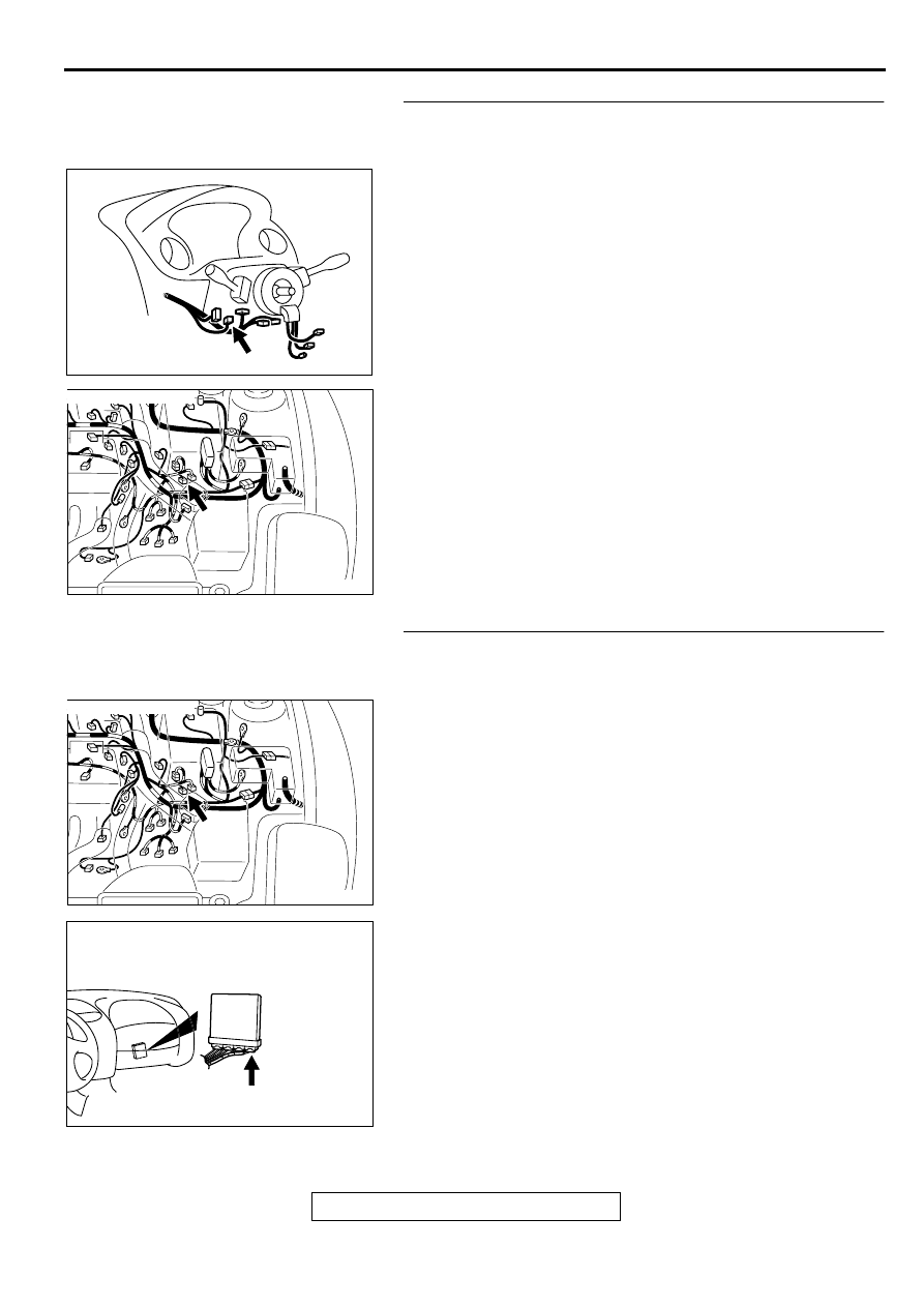
STEP 14. Check for harness damage between ignition 
switch connector C-87 terminal 2 and vehicle speed 
sensor connector B-39 terminal 1.
NOTE: Check harness after checking intermediate connectors 
B-36, C-28, C-78, C-104 and C-101 If intermediate connectors 
are damaged, repair or replace them. Refer to GROUP 00E, 
Harness Connector Inspection (

P.00E-2

). Then go to Step 17.

Q: Is the harness wire in good condition?

YES : Go to Step 15.
NO :  Repair it. Then go to Step 17.

STEP 15. Check for harness damage between vehicle 
speed sensor connector B-39 terminal 3 and ECM 
connector C-60 terminal 86.
NOTE: Check harness after checking intermediate connector 
B-36 If intermediate connector is damaged, repair or replace 
them. Refer to GROUP 00E, Harness Connector Inspection 
(

P.00E-2

). Then go to Step 17.

Q: Is the harness wire in good condition?

YES : Go to Step 16.
NO :  Repair it. Then go to Step 17.

AK000219

CONNECTOR:C-87

AC

AK000547AC

CONNECTOR:B-39

AK000547AC

CONNECTOR:B-39

AK000280

CONNECTOR:C-60

BI

MULTIPORT FUEL INJECTION (MFI) DIAGNOSIS

TSB Revision

MULTIPORT FUEL INJECTION (MFI) <2.4L ENGINE>

13A-288

STEP 16. Check for harness damage between vehicle 
speed sensor connector B-39 terminal 2 and ground.
NOTE: Check harness after checking intermediate connector 
B-36 If intermediate connector is damaged, repair or replace 
them. Refer to GROUP 00E, Harness Connector Inspection 
(

P.00E-2

). Then go to Step 17.

Q: Is the harness wire in good condition?

YES : Check for harness wire between vehicle speed 

sensor connector B-39 terminal 3 and other system 
because of short circuit to ground. Then go to Step 
17.

NO :  Repair it. Then go to Step 17.

STEP 17. Using scan tool MB991502, check data list item 
24: Vehicle Speed Sensor.

CAUTION

To prevent damage to scan tool MB991502, always turn the 
ignition switch to "LOCK" (OFF) position before 
connecting or disconnecting scan tool MB991502.
(1) Connect scan tool MB991502 to the data link connector.
(2) Start the engine.
(3) Set scan tool MB991502 to the data reading mode for item 

24, Vehicle Speed Sensor.

Check that the speedometer and MUT-II display speed 
match when traveling at a vehicle speed of 40km/h 
(25mph).

(4) Turn the ignition switch to the "LOCK" (OFF) position.

Q: Is the sensor operating properly?

YES : The inspection is complete.
NO :  Retry the troubleshooting.

DTC P0500: Vehicle Speed Sensor Malfunction <A/T>

TECHNICAL DESCRIPTION

When a malfunction of the vehicle speed sensor 
is detected, the transaxle control CPU inside the 
powertrain control module (PCM) outputs a 
malfunction signal to the engine control CPU in 
the PCM.

DTC SET CONDITIONS

Check Conditions, Judgment Criteria

Vehicle speed sensor failure signal is input to the 
engine control CPU from the transaxle control 
CPU.

TROUBLESHOOTING HINTS (The most likely 
causes for this code to be set are:)

Vehicle speed sensor failed.

Open or shorted vehicle speed sensor circuit, or 
loose connector.

PCM failed.

DIAGNOSIS

Required Special Tools
MB991502: Scan Tool (MUT-II)

AK000547AC

CONNECTOR:B-39

AKX01177

16 PIN

MB991502

AB

MULTIPORT FUEL INJECTION (MFI) DIAGNOSIS

TSB Revision

MULTIPORT FUEL INJECTION (MFI) <2.4L ENGINE>

13A-289

STEP 1. Using scan tool MB991502, read the A/T 
diagnostic trouble code (DTC).

CAUTION

To prevent damage to scan tool MB991502, always turn the 
ignition switch to the "LOCK" (OFF) position before 
connecting or disconnecting scan tool MB991502.
(1) Connect scan tool MB991502 to the data link connector.
(2) Turn the ignition switch to the "ON" position.
(3) Check the A/T-DTC.
(4) Turn the ignition switch to the "LOCK" (OFF) position.

Q: Is the A/T-DTC is output?

YES : Refer to GROUP 23A, Automatic Transaxle 

Diagnosis 

 Diagnostic Trouble Code Chart (

P.23A-

45

).

NO :  If DTC P0500 is output again after the MFI-DTC has 

been erased, replace the PCM. Then check that the 
DTC P0500 does not reset.

AKX01177

16 PIN

MB991502

AB

MULTIPORT FUEL INJECTION (MFI) DIAGNOSIS

TSB Revision

MULTIPORT FUEL INJECTION (MFI) <2.4L ENGINE>

13A-290

DTC P0506: Idle Control System RPM Lower Than Expected

AK000669

1 2
3 4

6

17

8

15

9

18

7

20

16

2

10

13

12

23 24 25 26

11

21

3

1

14

4

12

11

16

5 6

7 8

21

13
27

14
28

15
29

17
30

18
31

19
32

20
33

22
34

23
35

1

24

3

26

9

2

25

10

19

5

4

22

1 2
4 5 6

3

RED-

WHITE

RED-

WHITE

RED-

WHITE

RED

RED

RED

GREEN-BLA

CK

GREEN-RED

GREEN-WHITE

BLA

CK-YELLO

W

 C-49<M/T>
(MU803773)

 C-50<A/T>
(MU803784)

B-34

IDLE AIR
CONTROL(IAC)
MOTOR

A-21X

BATTERY

MFI
RELAY

1

1

2

2

3

3

4

4

5

6

ENGINE CONTROL
MODULE(ECM)<M/T>
OR
POWERTRAIN CONTROL
MODULE(PCM)<A/T>

4<M/T>
14<A/T>

17<M/T>
28<A/T>

5<M/T>
15<A/T>

18<M/T>
29<A/T>


Content   ..  145  146  147  148   ..