Mitsubishi Eclipse / Eclipse Spyder (2000-2002). Service and repair manual - part 114


  Index      Mitsubishi     Mitsubishi Eclipse / Eclipse Spyder (2000-2002). Service and repair manual


Search            


Content   ..  112  113  114  115   ..


Mitsubishi Eclipse / Eclipse Spyder (2000-2002). Service and repair manual - part 114


MULTIPORT FUEL INJECTION (MFI) DIAGNOSIS

TSB Revision

MULTIPORT FUEL INJECTION (MFI) <2.4L ENGINE>

13A-155

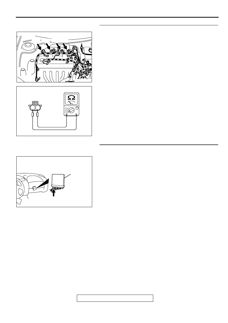
STEP 8. Check the injector.
(1) Disconnect each injector connector.
(2) Measure the resistance between injector side connector 

terminal 1 and 2.

Standard value: 13 

 16 ohm [at 20

°

 C (68

°

 F)]

Q: Is the resistance standard value?

YES : Go to Step 9.
NO :  Replace the injector. Then go to Step 14.

STEP 9. Check connector C-49 at ECM <M/T> or connector 
C-50 at PCM <A/T> for damage.
Q: Is the connector in good condition?

YES : Go to Step 10.
NO :  Repair or replace it. Refer to GROUP 00E, Harness 

Connector Inspection (

P.00E-2

). Then go to Step 14.

AK000273AB

AK000273

CONNECTOR : B-01, B-02, B-05, B-06 

B-01 B-02 B-05 B-06

AK000559

2

1

INJECTOR SIDE
CONNECTOR

AB

AK000280

C-49,C-50

ECM<M/T>
OR
PCM<A/T>

CONNECTORS:C-49<M/T>,C-50<A/T>

BC

MULTIPORT FUEL INJECTION (MFI) DIAGNOSIS

TSB Revision

MULTIPORT FUEL INJECTION (MFI) <2.4L ENGINE>

13A-156

STEP 10. Check for harness damage between injector 
connector and ECM connector <M/T> or PCM connector 
<A/T>.

a. Check the harness wire between injector connector B-01 

terminal 2 and ECM connector C-49 terminal 1 <M/T> or 
PCM connector C-50 terminal 1 <A/T> when checking No.1 
cylinder.

b. Check the harness wire between injector connector B-02 

terminal 2 and ECM connector C-49 terminal 14 <M/T> or 
PCM connector C-50 terminal 9 <A/T> when checking No.2 
cylinder.

c. Check the harness wire between injector connector B-05 

terminal 2 and ECM connector C-49 terminal 2 <M/T> or 
PCM connector C-50 terminal 24 <A/T> when checking 
No.3 cylinder.

d. Check the harness wire between injector connector B-06 

terminal 2 and ECM connector C-49 terminal 15 <M/T> or 
PCM connector C-50 terminal 2 <A/T> when checking No.4 
cylinder.

Q: Is the harness wire in good condition?

YES : Go to Step 11.
NO :  Repair it. Then go to Step 14.

STEP 11. Check the fuel pressure.
Refer to, Fuel Pressure Test (

P.13A-475

).

Q: Is the fuel pressure normal?

YES : Go to Step 12.
NO :  Repair or replace it. Then go to Step 14.

STEP 12. Check for entry of foreign matter (water, 
kerosene, etc.) into fuel.

Q: Are there any abnormalities?

YES : Go to Step 13.
NO :  Replace the fuel. Then go to Step 14.

STEP 13. Replace the injector.
(1) Replace the injector.
(2) Carry out a test drive with the drive cycle pattern. Refer to, 

Procedure 2 

 Fuel Trim Monitor (

P.13A-5

).

(3) Check the diagnostic trouble code (DTC).

Q: Is the DTC P0171 is output?

YES : Replace the ECM or PCM. Then go to Step 14.
NO :  The inspection is complete.

AK000273AB

AK000273

CONNECTOR : B-01, B-02, B-05, B-06 

B-01 B-02 B-05 B-06

AK000280

C-49,C-50

ECM<M/T>
OR
PCM<A/T>

CONNECTORS:C-49<M/T>,C-50<A/T>

BC

AK000273AB

AK000273

CONNECTOR : B-01, B-02, B-05, B-06 

B-01 B-02 B-05 B-06

MULTIPORT FUEL INJECTION (MFI) DIAGNOSIS

TSB Revision

MULTIPORT FUEL INJECTION (MFI) <2.4L ENGINE>

13A-157

STEP 14. Test the OBD-II drive cycle.
(1) Carry out a test drive with the drive cycle pattern. Refer to, 

Procedure 2 

 Fuel Trim Monitor (

P.13A-5

).

(2) Check the diagnostic trouble code (DTC).

Q: Is the DTC P0171 is output?

YES : Retry the troubleshooting.
NO :  The inspection is complete.

DTC P0172: System too Rich

Fuel Trim Circuit

Refer to, DTC P0201_P0204 Injector Circuit 
Malfunction (

P.13A-161

).

CIRCUIT OPERATION

Refer to, DTC P0201_P0204 Injector Circuit 
Malfunction (

P.13A-161

).

TECHNICAL DESCRIPTION

If a malfunction occurs in the fuel system, the fuel 
trim value becomes too small.

The ECM <M/T> or PCM <A/T> checks whether 
the fuel trim value is within a specified range.

DTC SET CONDITIONS

Check Conditions

Engine coolant temperature is lower than 
approximately 100

°

 C (212

°

 F) when the engine 

is started.

Intake air temperature is lower than 60

°

 C (140

°


F) when the engine is started.

Under the closed loop air/fuel ratio control.

Intake air temperature is higher than -10

° 

C (14

° 

F).

Barometric pressure is higher than 76kPa (11 
psi).

Volume air flow sensor output frequency is 88 Hz 
or more.

Judgment Criteria

Long-term fuel trim has continued to be lower 
than -12.5 for 2 seconds.

or

Short-term fuel trim has continued to be lower 
than -10.0 for 2 seconds.

Check Conditions

Engine coolant temperature is lower than 
approximately 100

°

 C (212

°

 F) when the engine 

is started.

Intake air temperature is lower than 60

°

 C (140

°


F) when the engine is started.

Under the closed loop air/fuel ratio control.

Intake air temperature is higher than -10

° 

C (14

° 

F).

Barometric pressure is higher than 76kPa (11 
psi).

Volume air flow sensor output frequency is 88 Hz 
or less.

Judgment Criteria

Long-term fuel trim has continued to be lower 
than -12.5 for 2 seconds.

or

Short-term fuel trim has continued to be lower 
than -15.0 for 2 seconds.

Check Conditions

Engine coolant temperature is higher than 
approximately 100

°

 C (212

°

 F) when the engine 

is started.

Intake air temperature is higher than 60

°

 C (140

°


F) when the engine is started.

Under the closed loop air/fuel ratio control.

Intake air temperature is higher than -10

° 

C (14

° 

F).

Barometric pressure is higher than 76kPa (11 
psi).

Volume air flow sensor output frequency is 88 Hz 
or more.

Judgment Criteria

Long-term fuel trim has continued to be lower 
than -12.5 for 2 seconds.

or

Short-term fuel trim has continued to be lower 
than -10.0 for 2 seconds.

Check Conditions

Engine coolant temperature is higher than 
approximately 100

°

 C (212

°

 F) when the engine 

is started.

Intake air temperature is higher than 60

°

 C (140

°


F) when the engine is started.

Under the closed loop air/fuel ratio control.

MULTIPORT FUEL INJECTION (MFI) DIAGNOSIS

TSB Revision

MULTIPORT FUEL INJECTION (MFI) <2.4L ENGINE>

13A-158

Intake air temperature is higher than -10

° 

C (14

° 

F).

Barometric pressure is higher than 76kPa (11 
psi).

Volume air flow sensor output frequency is 88 Hz 
or less.

Judgment Criteria

Long-term fuel trim has continued to be lower 
than -12.5 for 2 seconds.

or

Short-term fuel trim has continued to be lower 
than -15.0 for 2 seconds.

Check Conditions

Under the closed loop air/fuel ratio control.

The heated oxygen sensor (front) is active.

Judgment Criteria

Long-term fuel trim has continued to be lower 
than -12.5 for 2 seconds.

or

Short-term fuel trim has continued to be lower 
than -25.0 for 2 seconds.

TROUBLESHOOTING HINTS (The most likely 
causes for this code to be set are:)

Volume air flow sensor failed.

Injector failed.

Incorrect fuel pressure

Heated oxygen sensor failed.

Engine coolant temperature sensor failed.

Intake air temperature sensor failed.

Barometric pressure sensor failed.

Exhaust leak.

Use of incorrect or contaminated fuel.

ECM failed. <M/T>

PCM failed. <A/T>

DIAGNOSIS

Required Special Tools
MB991502: Scan Tool (MUT-II)

STEP 1. Using scan tool MB991502, check data list item 12: 
Volume Air Flow Sensor.

CAUTION

To prevent damage to scan tool MB991502, always turn the 
ignition switch to the "LOCK" (OFF) position before 
connecting or disconnecting scan tool MB991502.
(1) Connect scan tool MB991502 to the data link connector.
(2) Start the engine and run at idle.
(3) Set scan tool MB991502 to the data reading mode for item 

12, Volume Air Flow Sensor.

(4) Warm up the engine to normal operating temperature: 80

°


C to 96

°

 C(176

° 

F to 205

° 

F).

When idling, between 25 and 51 Hz (between 2.5 and 
5.0 g/s).

When 2,500 r/min, between 80 and 120 Hz (between 
8.5 and 12.7 g/s).

(5) Turn the ignition switch to the "LOCK" (OFF) position.

Q: Is the sensor operating properly?

YES : Go to Step 2.
NO :  Refer to, DTC P0101 

 Volume Air Flow Circuit 

Range/Performance Problem (

P.13A-26

), DTC P0102 

 Volume Air Flow Circuit Low Input (

P.13A-33

), DTC 

P0103 - Volume Air Flow Circuit High Input (

P.13A-

36

).

AKX01177

16 PIN

MB991502

AB


Content   ..  112  113  114  115   ..