Mitsubishi Eclipse / Eclipse Spyder (2000-2002). Service and repair manual - part 85


  Index      Mitsubishi     Mitsubishi Eclipse / Eclipse Spyder (2000-2002). Service and repair manual


Search            


Content   ..  83  84  85  86   ..


Mitsubishi Eclipse / Eclipse Spyder (2000-2002). Service and repair manual - part 85


MULTIPORT FUEL INJECTION (MFI) DIAGNOSIS

TSB Revision

MULTIPORT FUEL INJECTION (MFI) <2.4L ENGINE>

13A-39

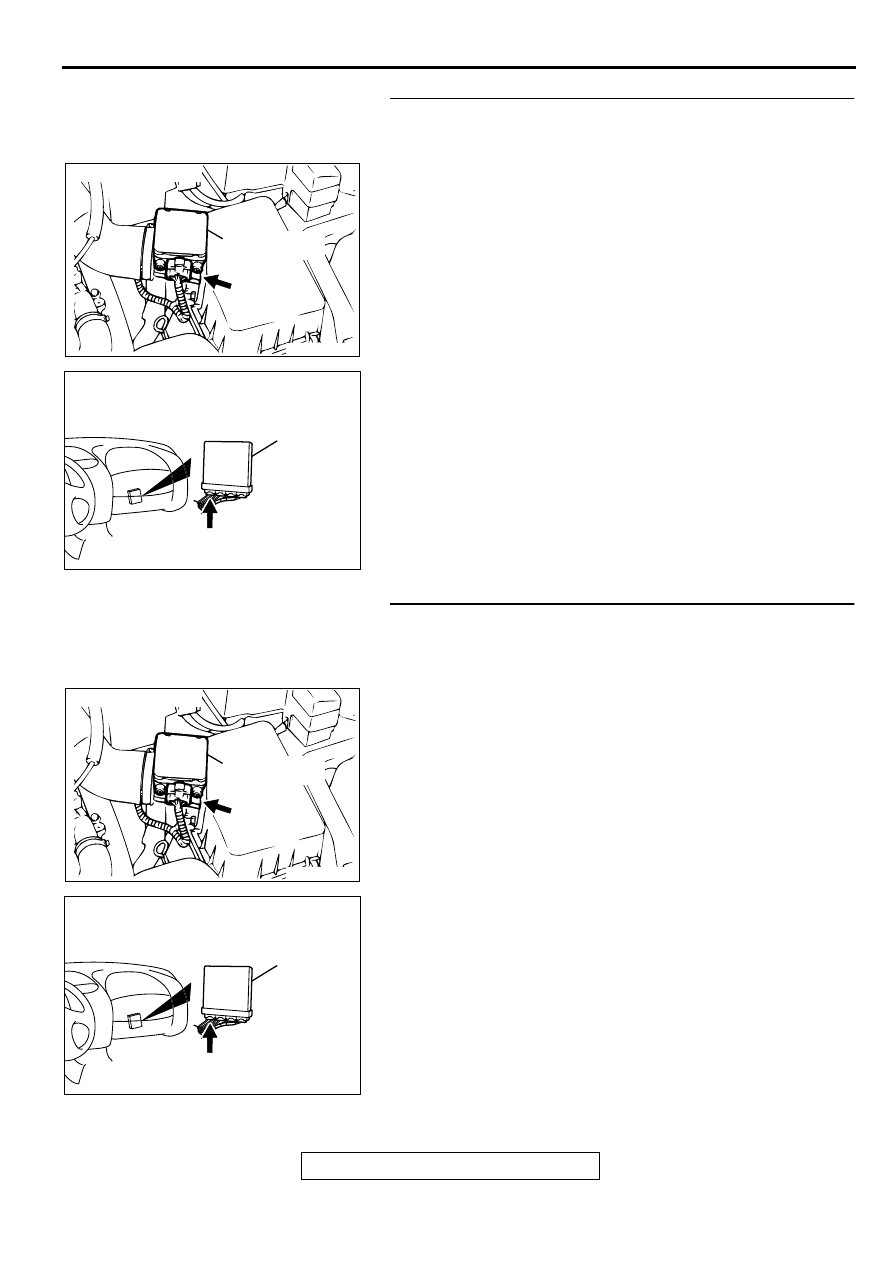
STEP 3. Check connector B-14 at volume air flow sensor 
and connector C-49 at ECM <M/T> or connector C-50 at 
PCM <A/T> for damage.
Q: Is the connector in good condition?

YES : Go to Step 4.
NO :  Repair or replace it. Refer to GROUP 00E, Harness 

Connector Inspection (

P.00E-2

). Then go to Step 9.

STEP 4. Check for short circuit to ground between volume 
air flow sensor connector B-14 terminal 7 and ECM 
connector C-49 terminal 19 <M/T> or PCM connector C-50 
terminal 19 <A/T>.
Q: Is the harness wire in good condition?

YES : Replace the volume air flow sensor. Then go to Step 

9. 

NO :  Repair it. Then go to Step 9.

ACX02480

CONNECTOR : B-14

AC

VOLUME AIR
FLOW SENSOR

AK000280

C-49,C-50

ECM<M/T>
OR
PCM<A/T>

CONNECTORS:C-49<M/T>,C-50<A/T>

BC

ACX02480

CONNECTOR : B-14

AC

VOLUME AIR
FLOW SENSOR

AK000280

C-49,C-50

ECM<M/T>
OR
PCM<A/T>

CONNECTORS:C-49<M/T>,C-50<A/T>

BC

MULTIPORT FUEL INJECTION (MFI) DIAGNOSIS

TSB Revision

MULTIPORT FUEL INJECTION (MFI) <2.4L ENGINE>

13A-40

STEP 5. Check the reset signal voltage at volume air flow 
sensor connector B-14 by backprobing.
(1) Do not disconnect the connector B-14.
(2) Start the engine and run at idle.
(3) Measure the voltage between terminal 7 and ground by 

backprobing.

When the engine idling, voltage should be 1.0 volt or 
less.

When the engine speed is 3000r/min, voltage should be 
between 6.0 and 9.0 volts.

(4) Turn the ignition switch to the "LOCK" (OFF) position.

Q: Is the voltage normal?

YES : Go to Step 8.
NO :  Go to Step 6.

STEP 6. Check connector B-14 at volume air flow sensor 
and connector C-49 at ECM <M/T> or connector C-50 at 
PCM <A/T> for damage.
Q: Is the connector in good condition?

YES : Go to Step 7.
NO :  Repair or replace it. Refer to GROUP 00E, Harness 

Connector Inspection (

P.00E-2

). Then go to Step 9.

AKX01515 AC

B-14 CONNECTOR
HARNESS
SIDE VIEW

1 2 3 4 5 6 7

ACX02480

CONNECTOR : B-14

AC

VOLUME AIR
FLOW SENSOR

AK000280

C-49,C-50

ECM<M/T>
OR
PCM<A/T>

CONNECTORS:C-49<M/T>,C-50<A/T>

BC

MULTIPORT FUEL INJECTION (MFI) DIAGNOSIS

TSB Revision

MULTIPORT FUEL INJECTION (MFI) <2.4L ENGINE>

13A-41

STEP 7. Check for open circuit and harness damage 
between volume air flow sensor connector B-14 terminal 7 
and ECM connector C-49 terminal 19 <M/T> or PCM 
connector C-50 terminal 19 <A/T>.
Q: Is the harness wire in good condition?

YES : Replace the ECM or PCM. Then go to Step 9.
NO :  Repair it. Then go to Step 9.

STEP 8. Replace the volume air flow sensor.
(1) Replace the volume air flow sensor.
(2) Carry out a test drive with the drive cycle pattern. Refer to, 

Procedure 6 

 Other Monitor (

P.13A-5

).

(3) Check the diagnostic trouble code (DTC).

Q: Is the DTC P0103 is output?

YES : Replace the ECM or PCM. Then go to Step 9.
NO :  The inspection is complete.

STEP 9. Test the OBD-II drive cycle.
(1) Carry out a test drive with the drive cycle pattern. Refer to, 

Procedure 6 

 Other Monitor (

P.13A-5

).

(2) Check the diagnostic trouble code (DTC).

Q: Is the DTC P0103 is output?

YES : Retry the troubleshooting.
NO :  The inspection is complete.

ACX02480

CONNECTOR : B-14

AC

VOLUME AIR
FLOW SENSOR

AK000280

C-49,C-50

ECM<M/T>
OR
PCM<A/T>

CONNECTORS:C-49<M/T>,C-50<A/T>

BC

ACX02480

CONNECTOR : B-14

AC

VOLUME AIR
FLOW SENSOR

MULTIPORT FUEL INJECTION (MFI) DIAGNOSIS

TSB Revision

MULTIPORT FUEL INJECTION (MFI) <2.4L ENGINE>

13A-42

DTC P0107: Barometric Pressure Circuit Low Input

CIRCUIT OPERATION

A 5-volt voltage is supplied to the barometric 
pressure sensor power terminal (terminal 1) from 
the ECM (terminal 81) <M/T> or PCM (terminal 
46) <A/T>. The ground terminal (terminal 5) is 
grounded with ECM (terminal 92) <M/T> or PCM 
(terminal 57) <A/T>.

A voltage that is proportional to the atmospheric 
pressure is sent to the ECM (terminal 85) <M/T> 
or PCM (terminal 55) <A/T> from the barometric 
pressure sensor output terminal (terminal 2).

AK000653

7

4 5 6

1 2 3

GREEN-YELLO

W

GREEN-WHITE

BLA

CK

 C-54<A/T>
(MU803781)

 C-60<M/T>
(MU803772)

ENGINE CONTROL
MODULE(ECM)<M/T>
OR
POWERTRAIN CONTROL
MODULE(PCM)<A/T>

81<M/T>
46<A/T>

5V

85<M/T>
55<A/T>

92<M/T>
57<A/T>

B-14

BAROMETRIC PRESSURE SENSOR
(INCORPORATED IN VOLUME AIR
FLOW SENSOR)

1

2

5

82

78

81

80

89 90 91 92

79

87

71

74

73

72

76

75

77

85

88

83 84

86

42 43
48 49 50 51 52 53 54 55 56 57

46

45

44

58 59

60 61 62 63

64 65 66

47

41

ACX02480

CONNECTOR : B-14

AF

BAROMETRIC
PRESSURE
SENSOR

AK000280

C-54

C-60

ECM<M/T>
OR
PCM<A/T>

CONNECTORS:C-60<M/T>,C-54<A/T>

BB


Content   ..  83  84  85  86   ..