Mitsubishi Eclipse / Eclipse Spyder (2000-2002). Service and repair manual - part 82
MULTIPORT FUEL INJECTION (MFI) DIAGNOSIS
TSB Revision
MULTIPORT FUEL INJECTION (MFI) <2.4L ENGINE>
13A-27
CIRCUIT OPERATION
•
The volume air flow sensor power is supplied
from the MFI relay (terminal 1), and the ground is
provided on the ECM (terminal 92) <M/T> or
PCM (terminal 57) <A/T>.
•
5-volt power is applied to the volume air flow
sensor output terminal (terminal 3) from the ECM
(terminal 90) <M/T> or PCM (terminal 65) <A/T>.
The volume air flow sensor generates a pulse
signal when the output terminal and ground are
opened/closed (opened/short).
TECHNICAL DESCRIPTION
•
While the engine is running, the volume air flow
sensor outputs a pulse signal which corresponds
to the volume of air flow.
•
The ECM <M/T> or PCM <A/T> checks whether
the frequency of this signal output by the volume
air flow sensor while the engine is running is at or
above the set value.
DTC SET CONDITIONS
Check Conditions
•
Engine speed is higher than 500 r/min.
Judgement Criteria
•
Volume air flow sensor output frequency has
continued to be 3.3 Hz or lower for 2 seconds.
TROUBLESHOOTING HINTS (The most likely
causes for this code to be set are:)
•
Volume air flow sensor failed.
•
Open or shorted volume air flow sensor circuit, or
loose connector.
•
ECM failed. <M/T>
•
PCM failed. <A/T>
•
Air leak between volume air flow sensor and
throttle body.
DIAGNOSIS
Required Special Tools
MB991502: Scan Tool (MUT-II)
ACX02480
CONNECTOR : B-14
AC
VOLUME AIR
FLOW SENSOR
AK000226
AK000226AB
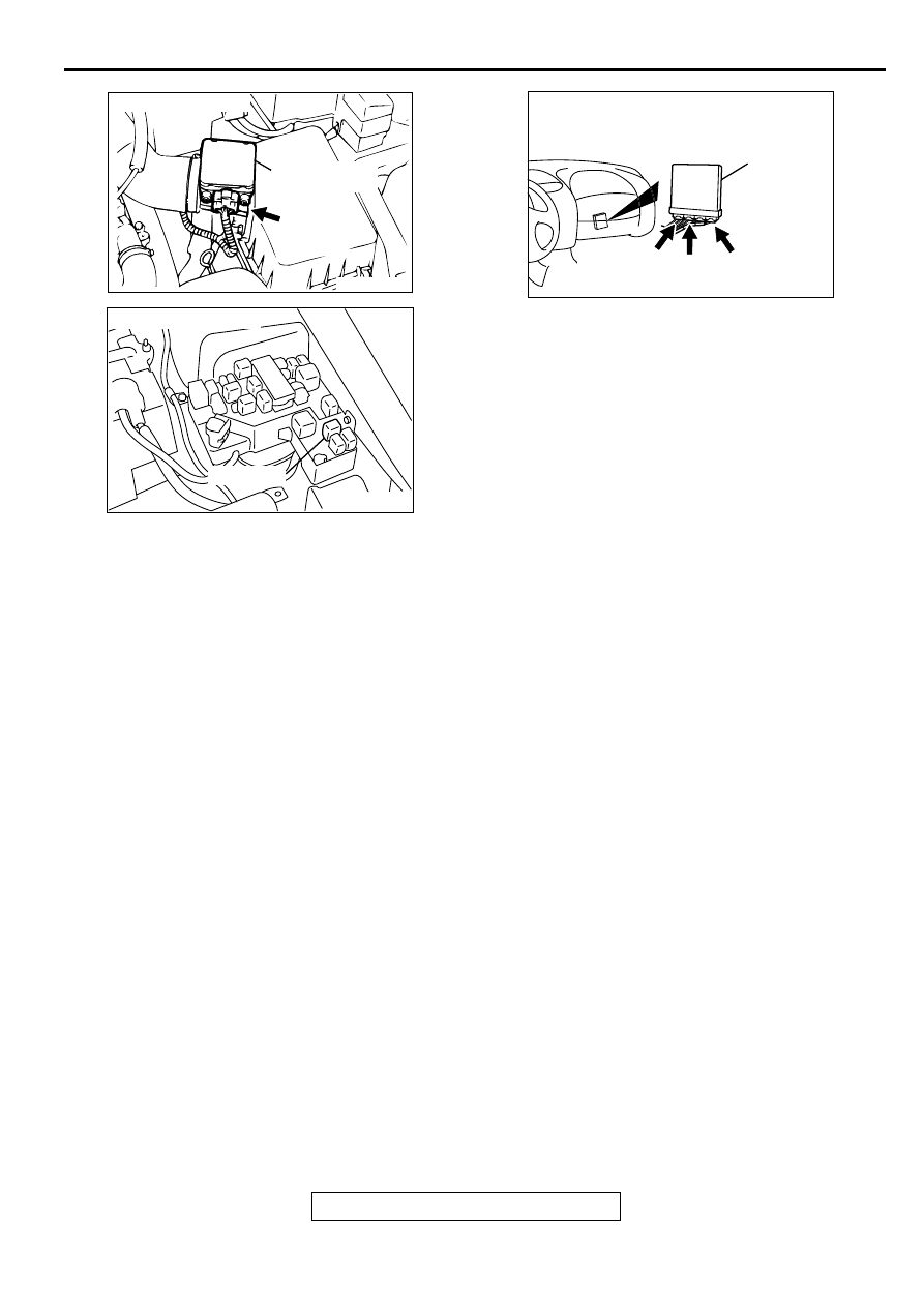
CONNECTOR : A-21X
MFI RELAY
AK000280
C-49,
C-50
C-54
C-60
ECM<M/T>
OR
PCM<A/T>
CONNECTORS:C-49,C-60<M/T>,
C-50,C-54<A/T>
BA