Mitsubishi Eclipse / Eclipse Spyder (2000-2002). Service and repair manual - part 34


  Index      Mitsubishi     Mitsubishi Eclipse / Eclipse Spyder (2000-2002). Service and repair manual


Search            


Content   ..  32  33  34  35   ..


Mitsubishi Eclipse / Eclipse Spyder (2000-2002). Service and repair manual - part 34


TIMING BELT

TSB Revision

ENGINE OVERHAUL <2.4L ENGINE>

11B-13

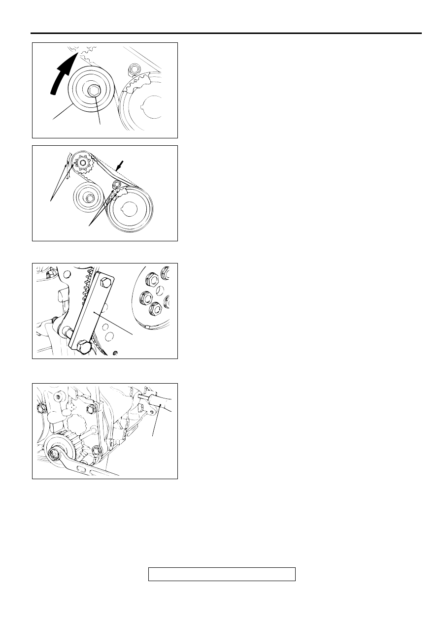
4. Move tensioner "B" in the direction of the arrow while lifting 

with your finger to give sufficient tension to the tension side 
of timing belt. In this condition, tighten the bolt to secure 
tensioner "B." When the bolt is tightened, use care to 
prevent the tensioner pulley shaft from turning with the bolt. 
If the shaft is turned with the bolt, the belt will be 
overtensioned.

Tightening torque: 19 

±

 3 N

m (14 

±

 2 ft-lb)

5. Check that timing marks on the sprockets are aligned with 

the timing marks on the front case.

6. With your index finger, press the midway of span on the 

tension side of timing belt "B." The bolt must deflect 5 

 7 

mm (0.20 - 0.28 inch).

>>F<< CRANKSHAFT BOLT TIGHTENING
1. Install special tool MD998781 to hold the flywheel or drive 

plate.

2. Install the washer and crankshaft bolt, and then tighten the 

bolt.

Tightening torque: 118 

±

 10 N

m (87 

±

 7 ft-lb)

>>G<< OIL PUMP SPROCKET INSTALLATION
1. Insert a Phillips head screwdriver [shank diameter 8 mm 

(0.3 inch)] through the plug hole on the left side of the 
cylinder block to block the left counterbalance shaft.

2. Install the oil pump sprocket.

3. Apply a thin coat of engine oil to the seating surface of the 

nut.

4. Tighten the nut to the specified torque.

Tightening torque: 54 

±

 5 N

m (40 

±

 4 ft-lb)

AKX00489

TENSIONER "B"

BOLT

AB

AKX00490

BELT DEFLECTION

TIMING
MARKS

TIMING
MARKS

AB

AKX00460

MD998781

AB

AKX00530

SCREW-
DRIVER

AB

TIMING BELT

TSB Revision

ENGINE OVERHAUL <2.4L ENGINE>

11B-14

>>H<< AUTO-TENSIONER INSTALLATION
If the auto-tensioner rod is fully extended, reset it as follows:
1. Clamp the auto-tensioner in a vise with soft jaws.

2. Push in the rod little by little with the vise until the set hole A 

in the rod is aligned with the hole B in the cylinder.

3. Insert a wire [1.4 mm (0.055 inch) in diameter] into the set 

holes. This auto-tensioner setting wire will be used during 
timing belt alignment.

4. Unclamp the auto-tensioner from the vise.

CAUTION

Leave the wire installed in the auto-tensioner.
5. Install the auto-tensioner onto the front case and tighten to 

the specified torque.

Tightening torque: 24 

±

 3 N

m (17 

±

 2 ft-lb)

>>I<< TIMING BELT INSTALLATION
1. Set the tensioner pulley so that the holes for attaching a 

wrench may be positioned as shown in the illustration.

AKX00479

AKX00480

A

B

AB

AKX00481

AKX00475

SMALL HOLE

AB

TIMING BELT

TSB Revision

ENGINE OVERHAUL <2.4L ENGINE>

11B-15

2. Align the timing mark on the camshaft sprocket with the 

timing mark on the rocker cover.

3. Align the timing mark on the crankshaft sprocket with the 

timing mark on the front case.

4. Align the timing mark on oil pump sprocket with its mating 

mark.

5. Remove the plug on the cylinder block and insert a Phillips 

head screwdriver [shank diameter 8 mm (0.3 inch)] through 
the hole.
If it can be inserted as deep as 60 mm (2.4 inches) or more, 
the timing marks are correctly aligned.
if the inserted depth is only 20 to 25 mm (0.8 to 0.9 inch), 
turn the oil pump sprocket one turn and realign the timing 
marks. then check to ensure that the screwdriver can be 
inserted 60 mm (2.4 inches) or more. keep the screwdriver 
inserted until the timing belt is completely installed.

6. Install the timing belt on the crankshaft sprocket, oil pump 

sprocket, idler pulley, camshaft sprocket, and tensioner 
pulley in that order.

AKX00584AB

TIMING
MARKS

AKX00582AB

TIMING MARKS

AKX00583AB

TIMING MARKS

AKX00469AB

PLUG

SCREWDRIVER

TIMING BELT

TSB Revision

ENGINE OVERHAUL <2.4L ENGINE>

11B-16

7. Lift up the tensioner pulley in the direction of arrow and 

tighten the center bolt. 

8. Check that all timing marks are aligned.

9. Remove the screwdriver inserted in step 5 and install the 

plug.

10.Turn the crankshaft a quarter turn counterclockwise. Then, 

turn it clockwise until the timing marks are aligned again.

11.Install special tool, MD998767 Socket Wrench and Torque 

Wrench, onto the tensioner pulley, and loosen the tensioner 
pulley center bolt.

NOTE: Use a torque wrench that can measure 0 to 5.0 N

(0 

 50 in-lb).

12.Torque to 3.5 N

m (30 in-lb) with the torque wrench.

13.Holding the tensioner pulley with special tool MD998767 

and torque wrench, tighten the center bolt to specification.

Tightening torque: 48 

±

 6 N

m (35 

±

 4 ft-lb)

14.Give two clockwise turns to the crankshaft. Wait for 15 

minutes, then proceed with the following inspection steps.

15.Check to see whether the metal wire inserted when the 

auto-tensioner was installed can be removed without any 
resistance.
If the metal wire can be removed without any resistance, it 
means that the belt has a proper tension. Therefore, remove 
the metal wire. In this condition, check that the rod 
protrusion of the auto-tensioner is within the standard value.

Standard value: 3.8 

 4.5 mm (0.15 

 0.17 inch)

16.If the metal wire offers resistance when removed, repeat the 

previous steps (10) through (15) until the standard value is 
obtained as measured by the rod projection of the auto-
tensioner rod.

AKX00591

AKX00592AB

MD998767

AKX00482

AKX00483AB

ROD PROTRUSION


Content   ..  32  33  34  35   ..