Mitsubishi Eclipse / Eclipse Spyder (2000-2002). Service and repair manual - part 24
ENGINE ASSEMBLY
TSB Revision
ENGINE MECHANICAL <2.4L ENGINE>
11A-13
AC001692
1
19
4.8 ± 1.0 N·m
44 ± 8 in-lb
20
17
16
2
3
18
4
14
15
9
8
7
6
5
10
11
12
19
O-RING
FUEL RAIL
ENGINE OIL
12 ± 2 N·m
100 ± 22 in-lb
21
AB
13
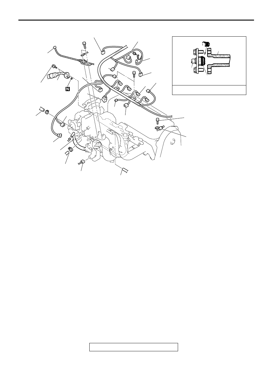
REMOVAL STEPS
1.
ACCELERATOR CABLE
CONNECTION
2.
PURGE HOSE CONNECTION
3.
BRAKE BOOSTER VACUUM
HOSE CONNECTION
4.
VACUUM HOSE CONNECTION
5.
IGNITION COIL CONNECTOR
6.
INJECTOR CONNECTOR
7.
IGNITION FAILURE SENSOR
CONNECTOR
8.
MANIFOLD DIFFERENTIAL
PRESSURE SENSOR
CONNECTOR
9.
THROTTLE POSITION SENSOR
CONNECTOR
10. HEATED OXYGEN SENSOR
(FRONT) CONNECTOR
11. CAPACITOR CONNECTOR
12. ENGINE COOLANT
TEMPERATURE SENSOR
CONNECTOR
13. CAMSHAFT POSITION
SENSOR CONNECTOR
14. KNOCK SENSOR CONNECTOR
15. ENGINE COOLANT
TEMPERATURE GAUGE UNIT
CONNECTOR
16. IDLE AIR CONTROL MOTOR
CONNECTOR
17. EVAPORATIVE EMISSION
PURGE SOLENOID VALVE
CONNECTOR
18. EGR SOLENOID VALVE
CONNECTOR
>>D<<
19. HIGH-PRESSURE FUEL HOSE
CONNECTION
20. FUEL RETURN HOSE
CONNECTION
21. PRESSURE HOSE
CONNECTION
REMOVAL STEPS (Continued)