Mitsubishi Eclipse. Technical Information Manual (1994) - part 55


  Index      Mitsubishi     Mitsubishi Eclipse. Technical Information Manual (1994)


Search            


Content   ..  53  54  55  56   ..


Mitsubishi Eclipse. Technical Information Manual (1994) - part 55


POWER TRAIN   Rear Axle <AWD>
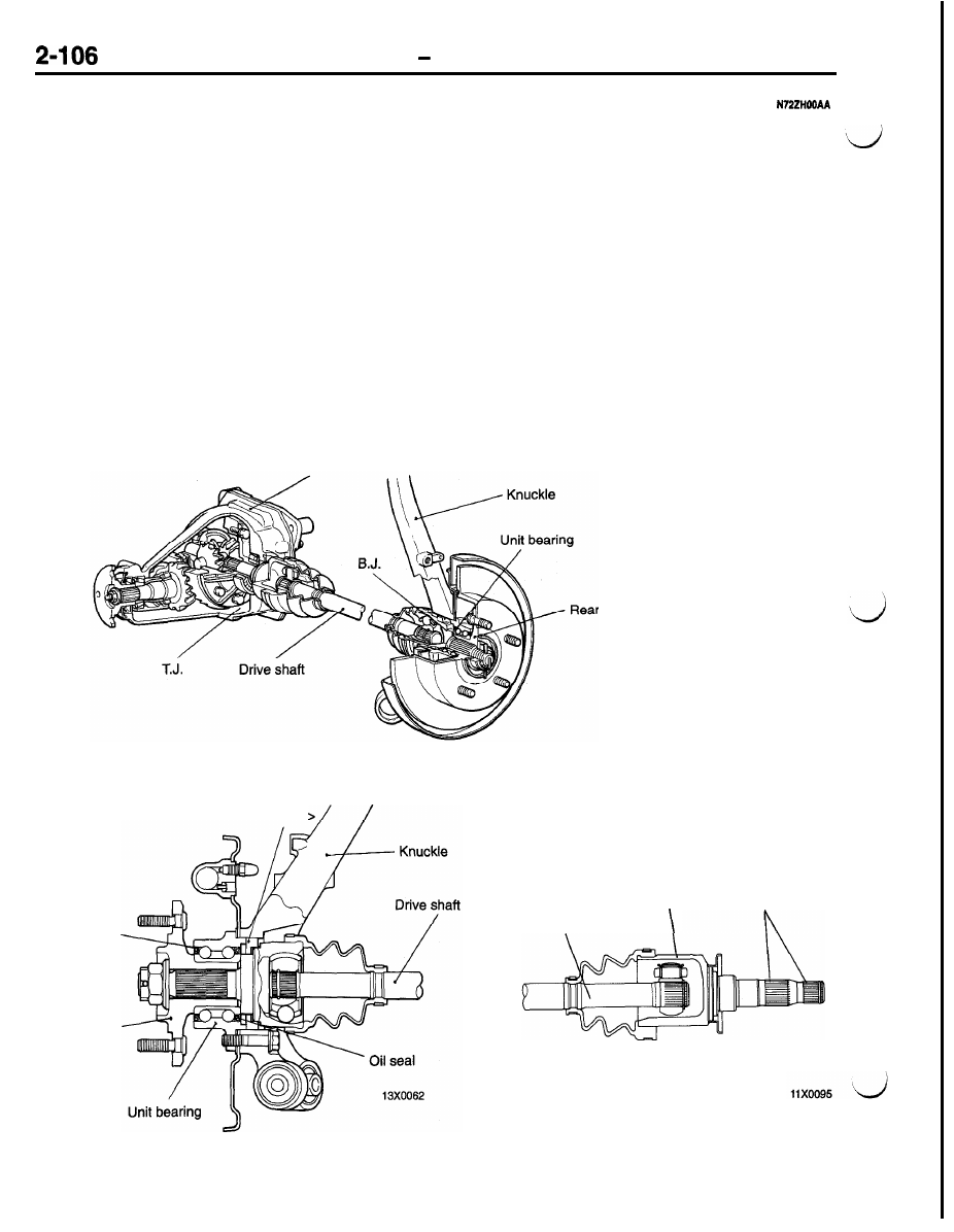
REAR  AXLE  <AWD>

The constant velocity joint on the differential side
of the drive shaft is a TJ type one which ensures
smooth inward-outward sliding movement. A BJ
type joint is used on the hub side.

FEATURES

l

The drive shaft is spline coupled on the different
side and serration coupled on the hub side,

eliminating the need for an axle shaft to allow

for simplicity around the hub.

l

The R.H. drive shaft on VCU type LSD equipped
vehicles has splines provided in two stages on
the T.J.

ABS equipped vehicles have a wheel speed

detection rotor on the drive shaft BJ outer race
and a speed sensor on the knuckle.

l

The unit bearing is press-fitted in the rear hub.

The unit bearing consists of inner and outer

races and an oil seal for lower rotating resistance

and higher protection against mud.

l

The rear hub assembly bolted to the knuckle
improves serviceability.

l

The differential carrier is elastically supported
via the bushing of the differential mount bracket
assembly at the front and via the bushings on
the cross member at the rear.

Differential carrier

Oil seal

Rear hub

Rotor <Vehicles with ABS

hub

11X0064

<Vehicles with  LSD>

T.J.

Drive shaft

Two splines

POWER TRAIN   Rear Axle 

DIFFERENTIAL

The differential uses a low frictional torque bearing

For better cooling of the differential during high-

and oil seal to provide improved power and fuel

speed operation, the differential carrier has cooling

efficiency.

fins.

In addition, VCU type LSD is used on some models.

SPECIFICATIONS

Conventional differential

Limited slip differential (VCU type)

Items

M/T

AK

AK

Reduction gear type

Hypoid gear

Reduction ratio

3.545

3.307

3.545

3.307

Differential gear type
(Type x number of gears)

Side gear

Straight bevel gear x 2

Straight bevel gear x 

Pinion gear

Straight bevel gear x 2

Straight bevel gear x 2

Number of teeth

Drive gear

39

43

39

43

Drive pinion

11

13

11

13

Side gear

14

14

14

16

Pinion gear

10

10

10

10

Bearing (outside diameter x
inside diameter)

mm (in.)

Side

72 x 35 (2.83 x 1.38)

Front

62 x 25 (2.44 x 

Rear

72 x 35 (2.83 x 1.38)

NOTE

 Denotes the gear (L.H.) which is in a single body with the viscous coupling.

Conventional differential

Cooling fin

11x0015

Limited slip differential (VCU type)

Rear crossmember

Differential mount

POWER TRAIN   Rear Axle 

DIFFERENTIAL SUPPORT

The front of the differential carrier is elastically 
ported by the bushing of the differential mount 

et assembly, and its rear is supported by the 
ings on the rear cross member.

11x0011


CONTENTS

N73ZAOOAA

ANTI-LOCK BRAKE SYSTEM (ABS)
<AWD>

. . . . . . . . . . . . . . . . . . . . ..*....a.....

44

ABS Electrical Circuit Diagram

. . . . . . . . . . . . . .

46

ABS Hydraulic Function Schematic

. . . . . . . . . .

47

Actuator

. . . . . . . . . . . . . . . . . . . . . . . . . . . . . . . . . . .

50

Electronic Control Unit (ECU)

. . . . . . . . . . . . . . .

51

Sensor

. . . . . . . . . . . . . . . . . . . . . . . . . . . . . . . . . . . .

48

System Drawing

. . . . . . . . . . . . . . . . . . . . . . . . . . .

45

ANTI-LOCK BRAKE SYSTEM (ABS)

. . . . . . . . . . . . . . . . . . . . . . . . . . . . . . . . . .

27

ABS Electrical Circuit Diagram

. . . . . . . . . . . . . .

29

ABS Hydraulic Pressure Function Diagram

... 30

Actuator

. . . . . . . . . . . . . . . . . . . . . . . . . . . . . . . . . . .

32

Electronic Control Unit (ECU)

. . . . . . . . . . . . . . .

34

Sensor

. . . . . . . . . . . . . . . . . . . . . . . . . . . . . . . . . . . .

31

System Drawing

. . . . . . . . . . . . . . . . . . . . . . . . . . .

28

BRAKES . . . . . . . . . . . . . . . . . . . . . . . . . . . . . . . .

22

Construction Diagram

. . . . . . . . . . . . . . . . . . . . . . 22

Features

. . . . . . . . . . . . . . . . . . . . . . . . . . . . . . . . . .

22

FRONT SUSPENSION

. . . . . . . . . . . . . . . . . 

3

Construction

. . . . . . . . . . . . . . . . . . . . . . . . . . . . . . . .

5

High-mounted upper arm

. . . . . . . . . . . . . . . . . 9

Optimized virtual kingpin axis positioning . . . 6

Shock absorber with damping force
control valve for very low and low
speed operation 

. . . . . . . . . . . . . . . . 10

Variation in camber during cornering . . . . . . 10

Features

. . . . . . . . . . . . . . . . . . . . . . . . . . . . . . . . . . .

3

Specifications

. . . . . . . . . . . . . . . . . . . . . . . . . . . . . . .

4

PARKING BRAKES . . . . . . . . . . . . . . . . . . . . . .

59

Construction Diagram . . . . . . . . . . . . . . . . . . . . . . . . 59

POWER STEERING

. . . . . . . . . . . . . . . . . . . . .

16

Construction

. . . . . . . . . . . . . . . . . . . . . . . . . . . . . . .

17

Features

. . . . . . . . . . . . . . . . . . . . . . . . . . . . . . . . . .

16

Oil Pump . . . . . . . . . . . . . . . . . . . . . . . . . . . . . . . . . .

20

Specifications

. . . . . . . . . . . . . . . . . . . . . . . . . . . . . .

16

Steering Gear and Linkage

. . . . . . . . . . . . . . . . . 21

Steering Shaft and Column

. . . . . . . . . . . . . . . . .

18

Steering Wheel

. . . . . . . . . . . . . . . . . . . . . . . . . . . .

18

REAR SUSPENSION

. . . . . . . . . . . . . . . . . . . .

11

Construction

. . . . . . . . . . . . . . . . . . . . . . . . . . . . . . .

13

Variation in toe angle by rearward force

input

. . . . . . . . . . . . . . . . . . . . . . . . . . . . . . . . . . .

14

Variation in toe angle by side forces

. . . . .

14

Variation in toe angle on turns

. . . . . . . . . . .

14

Features

. . . . . . . . . . . . . . . . . . . . . . . . . . . . . . . . . .

11

Specifications

. . . . . . . . . . . . . . . . . . . . . . . . . . . . . .

12

SERVICE BRAKES

. . . . . . . . . . . . . . . . . . . . . .

23

Brake Booster

. . . . . . . . . . . . . . . . . . . . . . . . . . . . .

25

Disc Brakes

. . . . . . . . . . . . . . . . . . . . . . . . . . . . . . .

26

Master Cylinder . . . . . . . . . . . . . . . . . . . . . . . . . . . .

24

Rear Drum Brakes . . . . . . . . . . . . . . . . . . . . . . . . . 26

Specifications

. . . . . . . . . . . . . . . . . . . . . . . . . . . . . .

23

SUSPENSION

. . . . . . . . . . . . . . . . . . . . . . . . . . . .

2

Features

. . . . . . . . . . . . . . . . . . . . . . . . . . . . . . . . . . .

2

WHEELS AND TIRES

. . . . . . . . . . . . . . . . . . .

15

Specifications

. . . . . . . . . . . . . . . . . . . . . . . . . . . . . .

15


Content   ..  53  54  55  56   ..