Mitsubishi Eclipse. Technical Information Manual (1994) - part 41
POWER TRAIN
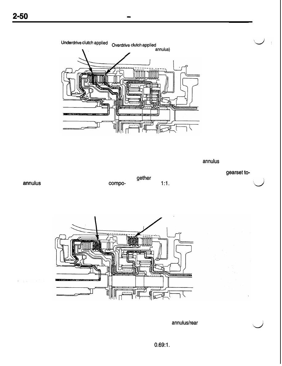
Automatic Transaxle
Third Gear
(turns rear sun)
(turns front carrier/rear
In third gear, two input clutches are applied to provide
torque input; the underdrive and overdrive clutches.
The underdrive clutch rotates the rear sun gear,
while the overdrive clutch rotates the front carrier/
rear
assembly. The result is two
nents (rear sun gear and rear
gear) rotating
at the same speed and in the same direction. This
effectively “locks” the entire planetary
and is rotated as one unit. The gear ratio
in third is
Fourth Gear
Overdrive clutch applied
(turns rear sun)
2-4
clutch applied
(holds front sun)
In fourth gear input torque is through the overdrive
clutch which drives the front carrier. The 2-4 clutch
is applied to hold the front sun gear. As the overdrive
clutch rotates the front carrier, it causes the pinions
of the front carrier to “walk around” the stationary
front sun gear. This causes the front carrier pinions
to turn the front
carrier assembly which
provides output torque. In fourth gear, transaxle
output speed is more than engine input speed. This
situation is called overdrive. Fourth gear (overdrive)
ratio is