Mitsubishi Eclipse. Technical Information Manual (1994) - part 39


  Index      Mitsubishi     Mitsubishi Eclipse. Technical Information Manual (1994)


Search            


Content   ..  37  38  39  40   ..


Mitsubishi Eclipse. Technical Information Manual (1994) - part 39


POWER TRAIN 

 Automatic Transaxle

CLUTCH
All flve clutches in the 

 transaxle are applied

hydraulically. Four of the clutches are released with

 springs, and one is released with a coil

spring. Three of the clutches supply input power
to the planetary geartrain and are called input
clutches. The other two clutches hold components
of the planetary geartrain and are called holding

clutches. With the exception of direct gear, one input
clutch and one holding clutch must be applied to 
obtain a gear range. In direct gear, two input clutches
are applied and basically connect the input and
output shafts together. This causes the entire 
set to rotate as one with no relative motion between
planetary 

 components.

C

Overdrive/Reverse 


 hub

Underdrive hub

rdrive

 thrust washer

 thrust

plate

Overdrive

Overdrive

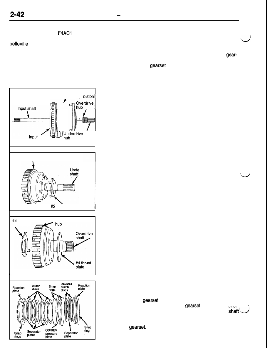
Input Clutch Assemblies

The input clutch assembly is located directly behind the oil
pump housing, and rides on the reaction shaft support journal.
The assembly consists of an input shaft, input hub, clutch

retainer, clutch pistons, an overdrive hub, an underdrive hub

and three input clutches. The clutches are the underdrive clutch,
overdrive clutch and reverse clutch. When the torque converter
turbine (which is splined to the input shaft) turns, the input
shaft, hub, and clutch retainer also turn.

Underdrive Clutch Hub

The underdrive clutch is splined to the underdrive hub assembly.
The underdrive hub and shaft assembly is splined to the rear

sun gear. When the underdrive clutch is applied the rear sun
gear is driven (rotated).

Overdrive Hub

The overdrive clutch is splined to the overdrive hub assembly
and the overdrive hub is splined to the front carrier assembly.
The reverse clutch is splined to the front sun gear assembly
and rotates it when applied.

Input Clutches
Each of the three clutches, in the input clutch assembly, have

the job of supplying input power to a particular component

in the planetary 

 when they are hydraulically applied.

They are connected to the planetary 

 through the over-

drive hub and shaft assembly, the underdrive hub and 
assembly, and the front sun gear assembly. When any of these
clutches are applied, they turn or drive a component in the

planetary 

POWER TRAIN 

 Automatic Transaxle

2-43

Underdrive Clutch

Underdrive

clutch

Rear sun

gear

Hub 

 Underdrive clutch

hub shaft

Input clutch

reiainer 

The underdrive clutch is located in the front of the

input clutch retainer. Line pressure is supplied to

the clutch from the valve body, through passages

in the case, oil pump and reaction shaft support.

The pressure then passes through a drilled passage

in the input clutch hub and to the front side of the
underdrive piston. The piston moves toward the
rear of the transaxle, compressing the clutch and

connecting it to the underdrive hub. The underdrive

hub is splined to the rear sun gear and turns it

when the clutch is engaged.

 line pressure is released, the clutch piston

returns with tension from the coil spring between

the piston and spring retainer. The piston has a
vent in it, and the spring retainer has a seal on

it. Both the vent and retainer seal are used to keep
oil on the back side of the piston. They counteract

the centrifugal pressure that develops when the
clutch is spinning. Centrifugal pressure can cause
the piston to move slightly and the clutch to drag
when the clutch is not actually being applied.

Overdrive Clutch

Overdrive clutch

Front planetary

carrier

Clutch retainer

Overdrive
clutch hub

2-44

POWER TRAIN   Automatic Transaxle

The overdrive clutch is the center clutch in the input
clutch assembly. The clutch pack is held on the

retainer, and the piston that applies the clutch is
located around the outside of the retainer. A pressure
plate in the rear of the clutch pack is used to com-
press the overdrive clutch when needed. Line pres-

sure from the valve body is directed through pas-
sages in the case, oil pump housing and reaction
shaft support. It is then directed through the input

hub and input clutch retainer to the back side of

Reverse Clutch

Hub

the 

 clutch piston. The pressure pushes

the piston forward and applies the overdrive clutch.
The clutch pack is compressed against the same

reaction plate that the underdrive clutch uses.

When applied, the overdrive clutch engages and
turns the overdrive hub, which is splined to the front
planetary carrier. When line pressure to the clutch

is released, the belleville spring on the front side

of the 

 piston returns the piston to its re-

leased position.

Reverse

clutch

Front sun
gear hub

The reverse clutch is located in the back of the

input clutch assembly. The reverse clutch is oper-
ated by the same piston, pressure plate and belleville

spring that operates the overdrive clutch. Line pres-
sure that applies the reverse clutch comes from
the valve body, directed through passages in the
case, oil pump and reaction shaft support. The line

pressure then goes through the input hub to the

front side of the 

 piston. The pressure

moves the piston to the back and compresses the
reverse clutch pack. When the clutch is applied,
it turns the front sun gear and hub assembly.

When line pressure to the reverse clutch is removed,
the belleville spring will pull the piston forward to

its released position. The 

 clutch piston

belleville spring is positioned so it will counter the
piston to prevent either the overdrive or reverse

clutches from dragging when they are not applied.

POWER TRAIN 

 Automatic Transaxle

2-45

Holding Clutches
2-4 Clutch

Front sun
gear hub

2-4 clutch

I

Transaxle case

Piston
retainer

Snao .

spring

Separator
plates

Piston

 discs

The 2-4 clutch is one of two clutches located in
the rear portion of the transaxle case. This clutch
sits behind the input clutch assembly. The 2-4 clutch/

piston retainer is in the front and held in place by
a snap ring. The 2-4 piston is located inside the

 2-4 clutch/piston retainer. A belleville spring is used

to return the piston after releasing the clutch. The
clutch pack comes next in the case. The reaction

plate is secured to the case using two snap rings.
The reaction plate for the 2-4 clutch is shared with
the Low Reverse clutch. When the 2-4 clutch is

applied hydraulically, it locks or secures the front
sun gear/hub assembly to the case so it does not
turn.
To apply the 2-4 clutch, line pressure is sent from
the valve body straight into the piston retainer. The
valve body has a rubber seal located on the top
of it that seals the valve body to the piston retainer.
When line pressure is removed and vented, th

belleville spring returns the 

 to release th

clutch.


Content   ..  37  38  39  40   ..