Mitsubishi Eclipse. Manual - part 691


  Index      Mitsubishi     Mitsubishi Eclipse - service repair manual 2004 year


Search            


Content   ..  689  690  691  692   ..


Mitsubishi Eclipse. Manual - part 691


AUTO-CRUISE CONTROL

TSB Revision

ENGINE AND EMISSION CONTROL

17-45

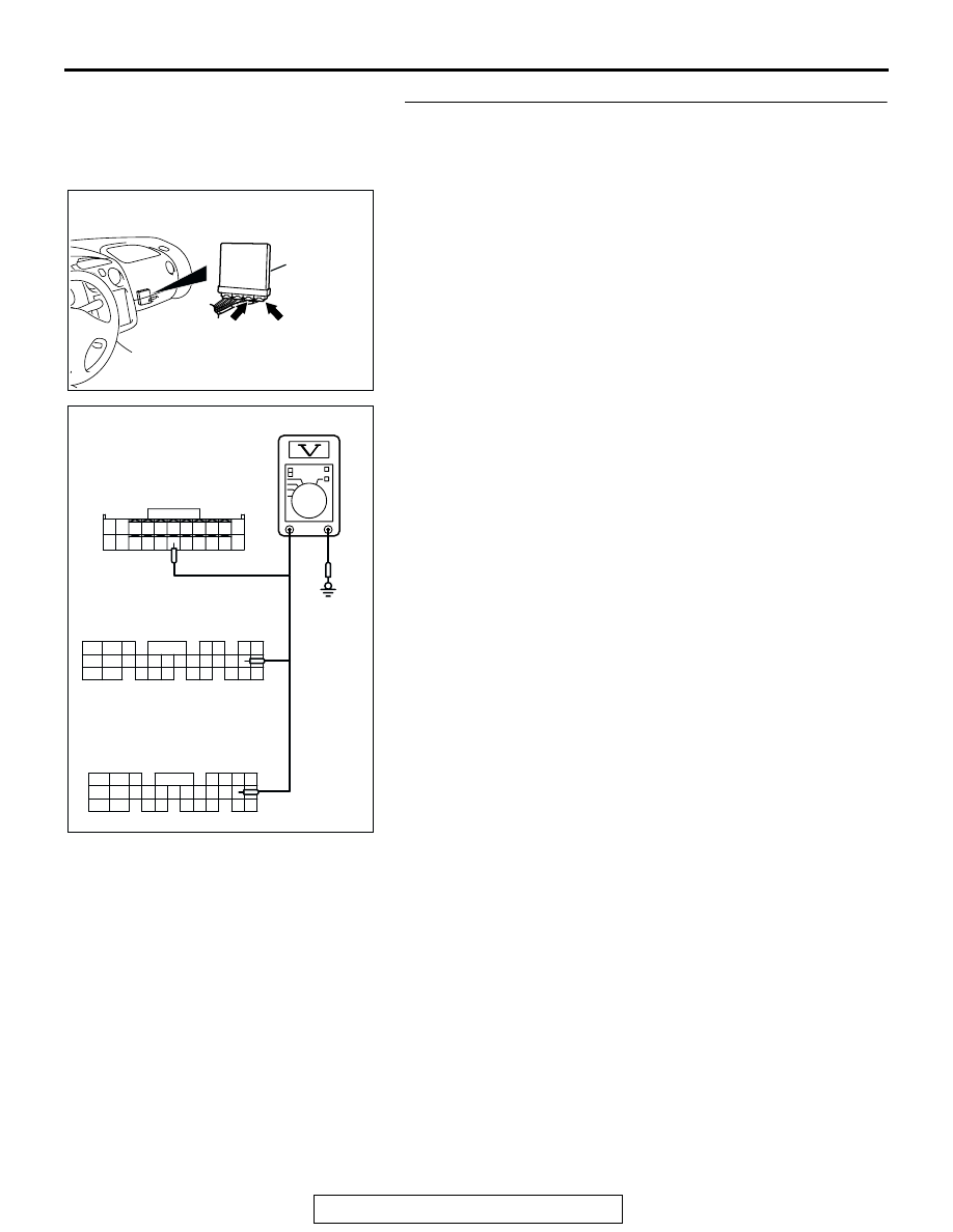
STEP 5. Measure the signal voltage at ECM connector C-60 
<2.4L engine-M/T> or C-62 <3.0L engine-M/T>, or PCM 
connector C-57 <2.4L engine-A/T> or C-59 <3.0L 
engine-A/T>.
(1) Disconnect ECM connector C-60 <2.4L engine-M/T> or 

C-62 <3.0L engine-M/T>, or PCM connector C-57 <2.4L 
engine-A/T> or C-59 <3.0L engine-A/T>.

(2) Turn the ignition switch to the "ON" position and the 

auto-cruise control MAIN switch to the "ON" position.

(3) Measure the voltage between ECM connector C-60 

terminal 87 <2.4L engine-M/T> or C-62 terminal 79 <3.0L 
engine-M/T>, or PCM connector C-57 terminal 79 <2.4L 
engine-A/T> or C-59 terminal 79 <3.0L engine-A/T> and 
ground.

• The voltage should measure between 4.0 and 5.5 volts.

(4) Turn the auto-cruise control MAIN switch to the "OFF" 

position and the ignition switch to the "LOCK" (OFF) 
position.

Q: Is the measured voltage between 4.0 and 5.5 volts?

YES : Check that DTC 17 is not set. If DTC 17 is not set, It 

can be assumed that this malfunction is intermittent. 
(Refer to GROUP 00, How to Use 
Troubleshooting/Inspection Service Points 

− How to 

Cope with Intermittent Malfunction 

P.00-6

). If DTC 17 

is set, replace the ECM <M/T> or PCM <A/T>, and 
then go to Step 9.

NO :  Go to Step 6.

AC203582AJ

CONNECTORS: C-60<2.4L ENGINE-M/T>, 
C-57<2.4L ENGINE-A/T>, C-62
<3.0L ENGINE-M/T>, C-59<3.0L ENGINE-A/T>

ECM <M/T>
OR
PCM <A/T>

C-60 (G), 
C-58 (GR)

C-57 (GR), 
C-59 (GR)

97

86

99

100

77

90

76

89

98

75

8887

95

83

96

8584

94

82

7473

81

91

78

92

93

72

79

80

71

91

92

81

85

74

88

90

8079

89

78

87

7776

86

75

82

71

84

73

83

72

AC203618

91

79

72

98

87

97

77

89

76

88

96

86

75

85

82

94

95

83

84

92

93

80

74

81

73

90

71

78

AC

C-60 <2.4L ENGINE-M/T>
HARNESS CONNECTOR:
COMPONENT SIDE

C-62 <3.0L ENGINE-M/T>
HARNESS CONNECTOR:
COMPONENT SIDE

C-57 <2.4L ENGINE-A/T>
C-59 <3.0L ENGINE-A/T>
HARNESS CONNECTOR:
COMPONENT SIDE

AUTO-CRUISE CONTROL

TSB Revision

ENGINE AND EMISSION CONTROL

17-46

STEP 6. Check auto-cruise control-ECU connector C-20, 
intermediate connector C-28 and ECM connector C-60 
<2.4L engine-M/T> or C-62 <3.0L engine-M/T>, or PCM 
connector C-57 <2.4L engine-A/T> or C-59 <3.0L 
engine-A/T> for loose, corroded or damaged terminals, or 
terminals pushed back in the connector.
Q: Are the connectors and terminals in good condition?

YES : Go to Step 7.
NO :  Repair or replace the faulty connector. (Refer to 

GROUP 00E, Harness Connector Inspection 

P.00E-2

). Go to Step 9.

AC001451

CONNECTOR: C-20

AB

AC101201AB

CONNECTOR: C-28

AC203582AJ

CONNECTORS: C-60<2.4L ENGINE-M/T>, 
C-57<2.4L ENGINE-A/T>, C-62
<3.0L ENGINE-M/T>, C-59<3.0L ENGINE-A/T>

ECM <M/T>
OR
PCM <A/T>

C-60 (G), 
C-58 (GR)

C-57 (GR), 
C-59 (GR)

AUTO-CRUISE CONTROL

TSB Revision

ENGINE AND EMISSION CONTROL

17-47

STEP 7. Check the harness wire between auto-cruise 
control-ECU connector C-20 terminal 2 and ECM connector 
C-60 terminal 87 <2.4L engine-M/T> or C-62 terminal 79 
<3.0L engine-M/T>, or PCM connector C-57 terminal 79 
<2.4L engine-A/T> or C-59 terminal 79 <3.0L engine-A/T> 
for damage.
Q: Is the harness wire in good condition?

YES : Go to Step 8.
NO :  Repair the damaged harness wire. Go to Step 9.

AC001451

CONNECTOR: C-20

AB

AC203582AJ

CONNECTORS: C-60<2.4L ENGINE-M/T>, 
C-57<2.4L ENGINE-A/T>, C-62
<3.0L ENGINE-M/T>, C-59<3.0L ENGINE-A/T>

ECM <M/T>
OR
PCM <A/T>

C-60 (G), 
C-58 (GR)

C-57 (GR), 
C-59 (GR)

AUTO-CRUISE CONTROL

TSB Revision

ENGINE AND EMISSION CONTROL

17-48

STEP 8. Measure the signal voltage at auto-cruise 
control-ECU connector C-20 by backprobing.
(1) Do not disconnect auto-cruise control-ECU connector C-20.
(2) Turn the ignition switch to the "ON" position and the 

auto-cruise control MAIN switch to the "ON" position.

(3) Measure the voltage between auto-cruise control-ECU 

connector C-20 terminal 2 and ground by backprobing.

• The voltage should measure between 4.0 and 5.5 volts. 

(When accelerator pedal is depressed.)

• The voltage should measure between 2.5 volts or less. 

(When accelerator pedal is released.)

(4) Turn the auto-cruise control MAIN switch to the "OFF" 

position and the ignition switch to the "LOCK" (OFF) 
position.

Q: Are all of the measured voltages satisfied?

YES : Check that DTC 17 is not set. If DTC 17 is not set, It 

can be assumed that this malfunction is intermittent. 
(Refer to GROUP 00, How to Use 
Troubleshooting/Inspection Service Points 

− How to 

Cope with Intermittent Malfunction 

P.00-6

). If DTC 17 

is set, replace the auto-cruise control-ECU (Refer to 

P.17-92

), and then go to Step 9.

NO :  Replace the auto-cruise control-ECU 

P.17-92

. Go to 

Step 9.

STEP 9. Check the diagnostic trouble codes.
Q: Is DTC 17 set?

YES : Go to Step 1.
NO :  This procedure is complete.

SYMPTOM CHART

M1172002300355

AC001451

CONNECTOR: C-20

AB

1 2 3 4 5 6 7 8

9 10 11 12 13 14 15 16

AC103150

C-20 CONNECTOR
HARNESS SIDE VIEW

AB

SYMPTOM

INSPECTION 
PROCEDURE NO.

REFERENCE PAGE

Communication with 
scan tool MB991958 
is not possible.

Communication with all 
systems is not possible.

2.4L Engine

-

Group 13A, 
diagnosis 

P.13A-737

3.0L Engine

-

Group 13B, 
diagnosis 

P.13B-908

Communication with auto-cruise 
control-ECU only is not possible.

1

P.17-50


Content   ..  689  690  691  692   ..