Mitsubishi Eclipse. Manual - part 690
AUTO-CRUISE CONTROL
TSB Revision
ENGINE AND EMISSION CONTROL
17-41
.
CIRCUIT OPERATION
The throttle position sensor signal and idle position
signal are sent to the auto-cruise control-ECU
through this circuit.
The throttle position sensor sends a voltage signal to
terminal 1 of the auto-cruise control-ECU. The volt-
age depends on throttle opening angle.
The auto-cruise control-ECU receives an idle posi-
tion signal from the ECM <M/T> or PCM <A/T> at
terminal 2. The signal is OFF when the accelerator
pedal is depressed, and ON when the accelerator
pedal is released.
.
DTC SET CONDITIONS
• The Idle position signal is ON and the throttle
position sensor voltage is 2.5 volts or more for
four seconds or more.
• The Idle position signal is OFF and the throttle
position sensor voltage is 0.2 volt or less for four
seconds or more.
.
TROUBLESHOOTING HINTS (The most likely
causes for this code to be set are:)
• Malfunction of the throttle position sensor.
• Damaged harness or connector.
• Malfunction of the auto-cruise control-ECU.
• Malfunction of the ECM <M/T> or PCM <A/T>.
DIAGNOSIS
Required Special Tools:
• MB991958: Scan Tool (MUT-III sub assembly)
• MB991824: Vehicle Communication Interface
• MB991827: MUT-III USB Cable
• MB991911: MUT-III Main Harness B
• MB991223: Harness Set
AC001451
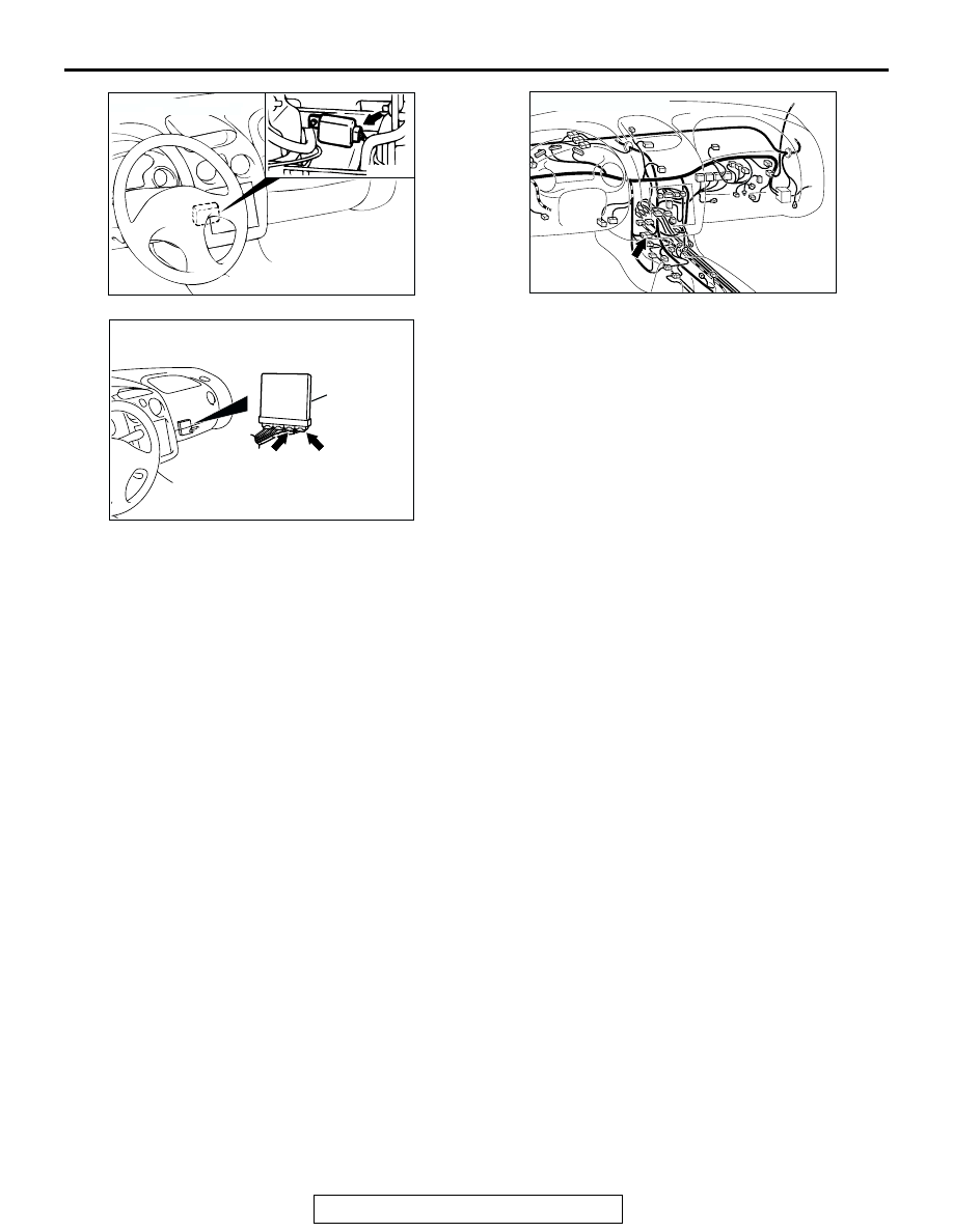
CONNECTOR: C-20
AB
AC101201AB
CONNECTOR: C-28
AC203582AJ
CONNECTORS: C-60<2.4L ENGINE-M/T>,
C-57<2.4L ENGINE-A/T>, C-62
<3.0L ENGINE-M/T>, C-59<3.0L ENGINE-A/T>
ECM <M/T>
OR
PCM <A/T>
C-60 (G),
C-58 (GR)
C-57 (GR),
C-59 (GR)