Mitsubishi Eclipse. Manual - part 658


  Index      Mitsubishi     Mitsubishi Eclipse - service repair manual 2004 year


Search            


Content   ..  656  657  658  659   ..


Mitsubishi Eclipse. Manual - part 658


SPECIAL TOOL

TSB Revision

INTAKE AND EXHAUST

15-3

INSPECTION PROCEDURE 2: Abnormal Noise 

DIAGNOSIS

STEP 1. Start the engine. Have an assistant stay 
in the driver’s seat. Raise the vehicle on a hoist. 
Have the assistant rev the engine while 
searching for exhaust leaks.

Q: Is any abnormal noise generated?

YES : 

Go to Step 2.

NO : 

This diagnosis is complete.

STEP 2. Check for missing parts in the muffler. 
Tap the muffler lightly to check for loose baffles, 
etc.

Q: Are there any missing parts in the muffler? 

YES : 

Replace, then go to Step 1.

NO : 

Go to Step 3.

STEP 3. Check the hanger for cracks.

Q: Is the hanger cracked?

YES : 

Replace, then go to Step 1.

NO : 

Go to Step 4.

STEP 4. Check for interference of the pipes and 
muffler with the body.

Q: Are the pipes and muffler interfering with the 

body?
YES : 

Repair, then go to Step 1.

NO : 

Go to Step 5.

STEP 5. Check the heat protectors.

Q: Are any heat protectors loose or damaged?

YES : 

Tighten or replace, then go to Step 1.

NO : 

Go to Step 6.

STEP 6. Check the pipes, catalytic converters 
and muffler for damage.

Q: Are the pipes, catalytic converters and muffler 

damaged?
YES : 

Replace, then go to Step 1. (For the 

removal of the catalytic converter, refer to 
GROUP 17 

P.17-120

.)

NO : 

There is no action to be taken.
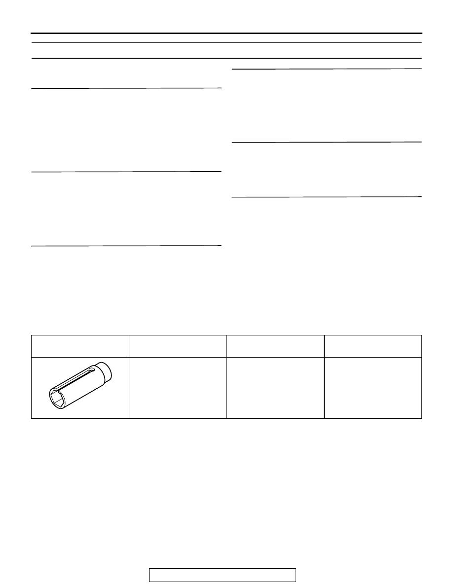
SPECIAL TOOL

M1151000600214

TOOL

TOOL NUMBER AND 
NAME

SUPERSESSION

APPLICATION

MD998770 
Oxygen sensor wrench

MD998770-01 or general 
service tool

Heated oxygen sensor 
removal and installation

ON-VEHICLE SERVICE

TSB Revision

INTAKE AND EXHAUST

15-4

ON-VEHICLE SERVICE

INTAKE MANIFOLD TUNING SYSTEM CHECK 
<3.0L ENGINE 

 WITH INTAKE MANIFOLD 

TUNING SYSTEM>

M1151001700043

1. Warm up the engine. 
2. Disconnect the vacuum hose from the intake manifold tuning 

(IMT) actuator, and then connect a vacuum gauge via the 
Tee-fitting.

3. Start the engine and verify that a vacuum is applied to the 

vacuum gauge.

4. As described in the chart below, vary the engine speed to 

inspect the vacuum conditions. During this inspection, verify 
that the rod of the IMT actuator is operating.

INTAKE MANIFOLD TUNING SOLENOID CHECK 
<3.0L ENGINE 

 WITH INTAKE MANIFOLD 

TUNING SYSTEM>

M1151010000031

1. Disconnect the vacuum hoses from the intake manifold 

tuning (IMT) solenoid.
NOTE: When disconnecting the vacuum hose, always make 
sure that it can be reconnected at its original position.

2. Disconnect the harness connector.
3. Connect a hand vacuum pump to nipple (B) of the IMT 

solenoid.

4. As described in the chart below, check airtightness by 

applying a vacuum with voltage applied directly from the 
battery to the IMT solenoid, and without applying voltage.

ENGINE SPEED

NORMAL 
CONDITION

CONTROL 
VALVE

4,000 rpm or less

Vacuum 
maintained

Closed

Form 4,000 rpm or less, 
engine is suddenly

Vacuum not 
change

Closed

4,250 rpm or more

Vacuum leaks

Open

AK102971

INTAKE MANIFOLD
TUNING ACTUATOR

INTAKE MANIFOLD
TUNING SOLENOID

AK102971AC

VACUUM GAUGE

BATTERY POSITIVE 
VOLTAGE

NIPPLE (A) 
CONDITION

NORMAL 
CONDITION

Applied

Open

Vacuum leaks

Closed

Vacuum 
maintained

Not applied

Open

Vacuum leaks

AK102947

B

A

AK102947AB

ON-VEHICLE SERVICE

TSB Revision

INTAKE AND EXHAUST

15-5

5. Measure the resistance between the terminals of the IMT 

solenoid.

Standard value: 29 

 35  [at 20°C (68°F)]

6. Replace solenoid resistance is out of specification.

VACUUM TANK CHECK <3.0L ENGINE 

 WITH 

INTAKE MANIFOLD TUNING SYSTEM>

M1151010100038

1. Disconnect the vacuum hoses from the vacuum tank.

NOTE: When disconnecting the vacuum hose, always make 
sure that it can be reconnected at its original position.

2. Connect a hand vacuum pump to nipple "A" of the vacuum 

tank, apply a vacuum of 67 kPa (19.7 in. Hg), and verify that 
the vacuum is maintained.

3. Disconnect the hand vacuum pump from nipple "A" and 

connect it to nipple "B".

4. Block nipple "A" with your finger and apply a vacuum of 67 

kPa (19.7 in. Hg) to nipple "B". Release your finger from 
nipple "A" and verify that the vacuum leaks immediately.

5. Replace the vacuum tank if it is faulty.

AK102948

AK102949

AK102949AB

A

B

AIR CLEANER

TSB Revision

INTAKE AND EXHAUST

15-6

AIR CLEANER

REMOVAL AND INSTALLATION

M1151002100464

Pre-removal and Post-installation Operation
Battery Removal and Installation (Refer to GROUP 54A, 
Battery 

P.54A-8

.)

AC001421

<2.4L ENGINE>

<3.0L ENGINE>

5

4

3.9 ± 1.0 N·m
38 ± 8 in-lb

3.9 ± 1.0 N·m
38 ± 8 in-lb

1

2

8.8 ± 1.0 N·m
78 ± 9 in-lb

8.8 ± 1.0 N·m
78 ± 9 in-lb

6

8

7

3

9

4

1

3.9 ± 1.0 N·m
38 ± 8 in-lb

3.9 ± 1.0 N·m
38 ± 8 in-lb

8.8 ± 1.0 N·m
78 ± 9 in-lb

8.8 ± 1.0 N·m
78 ± 9 in-lb

2

3

10

7

8

5

6

AB

REMOVAL STEPS

1.

AIR INTAKE HOSE

2.

RESONATOR A

3.

AIR DUCT

4.

VOLUME AIRFLOW SENSOR 
ASSEMBLY

5.

AIR CLEANER HOUSING 
COVER

6.

AIR CLEANER ELEMENT

7.

AIR CLEANER HOUSING

8.

AIR CLEANER BRACKET

9.

RESONATOR B <2.4L ENGINE>

10. RESONATOR C <3.0L ENGINE>

REMOVAL STEPS (Continued)


Content   ..  656  657  658  659   ..