Mitsubishi Eclipse. Manual - part 629


  Index      Mitsubishi     Mitsubishi Eclipse - service repair manual 2004 year


Search            


Content   ..  627  628  629  630   ..


Mitsubishi Eclipse. Manual - part 629


MULTIPORT FUEL INJECTION (MFI) DIAGNOSIS

TSB Revision

MULTIPORT FUEL INJECTION (MFI) <3.0L>

13B-1059

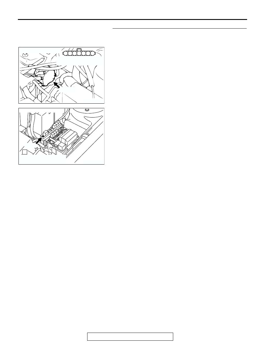
STEP 8. Check for open circuit between distributor 
connector B-22 (terminal No. 2) and engine speed 
detection connector A-12X (terminal No. 1).
Q: Is the harness wire in good condition?

YES : Replace the ECM or PCM. Then confirm that the 

malfunction symptom is eliminated.

NO :  Repair it. Then confirm that the malfunction symptom 

is eliminated.

AK300439

3

4

5

1

2

6

7

B-22 (B)

AB

CONNECTOR: B-22

HARNESS CONNECTOR:
COMPONENT SIDE

AK300747

1

CONNECTOR: A-12X

AB

A-12X

HARNESS CONNECTOR:
COMPONENT SIDE

MULTIPORT FUEL INJECTION (MFI) DIAGNOSIS

TSB Revision

MULTIPORT FUEL INJECTION (MFI) <3.0L>

13B-1060

INSPECTION PROCEDURE 34: A/C system.

.

COMMENT

• When the A/C is "ON", the battery positive volt-

age is applied on the ECM (terminal 83) <M/T> 
PCM (terminal 83) <A/T> from the automatic 
compressor controller. 
When battery positive voltage is applied to the 
ECM <M/T> or PCM <A/T>, the ECM <M/T> or 
PCM <A/T> turns "ON" the power transistor in the 
ECM <M/T> or PCM <A/T>. The ECM <M/T> or 
PCM <A/T> delays A/C engagement momentarily 
while it increases idle rpm. Then the A/C com-
pressor clutch relay coil will be energized. 

With this, the A/C compressor clutch relay turns 
"ON", and the A/C compressor clutch functions.

.

TROUBLESHOOTING HINTS (The most likely 
causes for this case: )

• Malfunction of the A/C control system.

• Malfunction of the A/C switch.

• Improper connector contact, open circuit or 

short-circuited harness wire.

• Malfunction of the ECM <M/T> or PCM <A/T>.

AK000721

GREEN-

RED

GREEN

ENGINE CONTROL
MODULE (ECM) <M/T>
OR
POWERTRAIN CONTROL
MODULE (PCM) <A/T>

83 <M/T>*2
83 <A/T>*4

20 <M/T>*1
20 <A/T>*3

A/C COMPRESSOR
RELAY

NOTE
*1:ECM connector C-51 <M/T>
*2:ECM connector C-62 <M/T>
*3:PCM connector C-52 <A/T>
*4:PCM connector C-59 <A/T>

AUTOMATIC
COMPRESSOR
CONTROLLER

98

78

71

88 89

76 77

72
79
91

73
80

74

75

81
92

82 83
93

84 85

94

86 87

95 96

90

80

87

81

94

85

82

84

93

86

98

99

74

92

73

83

88

91

95

97

96

100

89

78

71

90

76 77

75

72
79

97

C-62 <M/T>
(MU803783)

C-59 <A/T>
(MU803782)

C-51 <M/T>, C-52 <A/T>

(MU803784)

2

3 4

5 6

7 8

9

11 12 13 14 15 16 17 18 19 20

30

21 22 23

24 25

26 27 28 29

3132 33

34 35

1

10

A/C Circuit

AK000225

CONNECTORS : C-51, C-62<M/T>,
C-52, C-59<A/T>

C-52

C-51

PCM<A/T>

ECM<M/T>

AM

C-59

C-62

MULTIPORT FUEL INJECTION (MFI) DIAGNOSIS

TSB Revision

MULTIPORT FUEL INJECTION (MFI) <3.0L>

13B-1061

DIAGNOSIS

STEP 1. Check connector C-51, C-62 at ECM <M/T> or 
connector C-52, C-59 at PCM <A/T> for damage.
Q: Is the connector in good condition?

YES : Go to Step 2.
NO :  Repair or replace it. Refer to GROUP 00E, Harness 

Connector Inspection 

P.00E-2

. Then confirm that the 

malfunction symptom is eliminated.

STEP 2. Check the circuit at ECM connector C-51 <M/T> or 
PCM connector C-52 <A/T>.
(1) Disconnect the connectors C-51 <M/T> or C-52 <A/T> and 

measure at the harness side.

(2) Turn the ignition switch to the "ON" position.
(3) Measure the voltage between terminal 20 and ground.

• Voltage should be battery positive voltage.

(4) Using a jumper wire, connect terminal 20 to ground.

• A/C compressor relay should turn "ON".

(5) Turn the ignition switch to the "LOCK" (OFF) position.
Q: Is the voltage and A/C compressor relay condition 

normal?
YES : 
Go to Step 3.
NO :  Refer to GROUP 55, Diagnosis 

− Introduction To 

Heater, Air Conditioning And Ventilation Diagnosis 

P.55-4

. Then confirm that the malfunction symptom is 

eliminated.

AK000225

CONNECTORS : C-51, C-62<M/T>,
C-52, C-59<A/T>

C-52

C-51

PCM<A/T>

ECM<M/T>

AM

C-59

C-62

AKX01448 AH

1

2

3

4

5

6

7

8

9

10

11

12

13

14

15

16

17

18

19 20 21

22

23

24

25

26

28

29

30

31

32

33

34

35

36

C-51<M/T>,C-52<A/T>
HARNESS SIDE
CONNECTOR

MULTIPORT FUEL INJECTION (MFI) DIAGNOSIS

TSB Revision

MULTIPORT FUEL INJECTION (MFI) <3.0L>

13B-1062

STEP 3. Check the circuit at ECM connector C-62 <M/T> or 
PCM connector C-59.
(1) Disconnect the connectors C-62 <M/T> or C-59 <A/T> and 

measure at the harness side.

(2) Turn the ignition switch to the "ON" position.
(3) Measure the voltage between terminal 83 and ground.

• Voltage should be 1 volt or less when the A/C switch is 

"OFF".

• Voltage should be battery positive voltage when the A/C 

switch is "ON".

(4) Turn the ignition switch to the "LOCK" (OFF) position.
Q: Is the voltage normal?

YES : Replace the ECM or PCM. Then confirm that the 

malfunction symptom is eliminated.

NO :  Refer to GROUP 55, Diagnosis 

− Introduction To 

Heater, Air Conditioning And Ventilation Diagnosis 

P.55-4

DATA LIST REFERENCE TABLE

M1131152000876

CAUTION

• When shifting the select lever to D range, the brakes should be applied so that the vehicle does 

not move forward.

• Driving tests always need two persons: one driver and one observer.

NOTE: Sensor 1 indicates the sensor mounted at a position closest to the engine, and sensor 2 indicates the 
sensor mounted at the position second close to the engine.
NOTE: Bank 1 indicates the right bank cylinder, and bank 2 indicates the left bank cylinder.
NOTE: 

*1: 

If the idle speed is lower than the standard value on a very cold engine [approximately -20

°

(-4

°

F)] even when the IAC motor is fully opened, the air volume limiter built in the throttle body could be 

defective.
NOTE: 

*2:

 In a new vehicle [driven approximately 500 km (311 mile) or less], the step of the stepper motor is 

sometimes 30 steps greater than the standard value.
NOTE: 

*3: 

The injector drive time represents the time when the cranking speed is at 250 r/min or below when 

the power supply voltage is 11 volts.
NOTE: 

*4:

 In a new vehicle [driven approximately 500 km (311 mile) or less], the injector drive time is some-

times 10% longer than the standard time.
NOTE: 

*5

: In a new vehicle [driven approximately 500 km (311 mile) or less], the volume airflow sensor output 

frequency is sometimes 10% higher than the standard frequency.
NOTE: 

*6

: Applicable to GST

AK000389

71

72

73

74

75

76

77

78

79

80

81

82

83

84

85

86

87

88

89

90

91

92

93

94

95

96

97

98

99

100

C-62 HARNESS
SIDE CONNECTOR

AC

<M/T>

AKX01449

<A/T>

C-59 HARNESS
SIDE CONNECTOR

71

72

73

74

75

76

77

78

79

80

81

82

83

84

85

86

87

88

89

90

91

92

93

94

95

96

97

98

AH


Content   ..  627  628  629  630   ..