Mitsubishi Eclipse. Manual - part 628


  Index      Mitsubishi     Mitsubishi Eclipse - service repair manual 2004 year


Search            


Content   ..  626  627  628  629   ..


Mitsubishi Eclipse. Manual - part 628


MULTIPORT FUEL INJECTION (MFI) DIAGNOSIS

TSB Revision

MULTIPORT FUEL INJECTION (MFI) <3.0L>

13B-1055

.

CIRCUIT OPERATION

• The battery positive voltage is applied on the igni-

tion coil by the ignition switch-IG.

• When the ECM <M/T> or PCM <A/T> turns the 

power transistor in the ECM <M/T> or PCM 
<A/T> "OFF", battery positive voltage is applied 
on the ignition power transistor (terminal No. 3), 
and the ignition power transistor turns "ON".

• When the ignition power transistor turns on, the 

ignition coil's primary circuit is grounded by the 
ignition power transistor terminal No. 4. Then the 
primary current flows to the ignition coil.

.

TROUBLESHOOTING HINTS (The most likely 
causes for this case: )

• Malfunction of the ignition coil.

• Malfunction of the ignition power transistor.

• Improper connector contact, open circuit or 

short-circuited harness wire.

• Malfunction of the ECM <M/T> or PCM <A/T>.

DIAGNOSIS

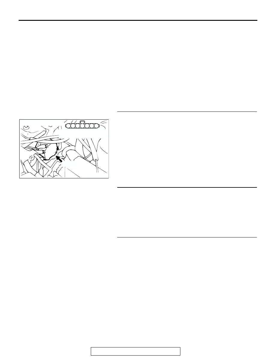
STEP 1. Check connector B-22 at distributor for damage.
Q: Is the connector in good condition?

YES : Go to Step 2.
NO :  Repair or replace it. Refer to GROUP 00E, Harness 

Connector Inspection 

P.00E-2

. Then confirm that the 

malfunction symptom is eliminated.

STEP 2. Check the ignition coil.
Refer to GROUP 16, Ignition System 

− On-vehicle service − 

Ignition coil check 

P.16-38

.

Q: Are there any abnormalities?

YES : Go to Step 3.
NO :  Repair the ignition coil. Then confirm that the 

malfunction symptom is eliminated.

STEP 3. Check the ignition power transistor.
Refer to GROUP 16, Ignition System 

− On-vehicle service − 

Power transistor check 

P.16-38

.

Q: Are there any abnormalities?

YES : Go to Step 4.
NO :  Repair the ignition power transistor. Then confirm that 

the malfunction symptom is eliminated.

AK300439

3

4

5

1

2

6

7

B-22 (B)

AB

CONNECTOR: B-22

HARNESS CONNECTOR:
COMPONENT SIDE

MULTIPORT FUEL INJECTION (MFI) DIAGNOSIS

TSB Revision

MULTIPORT FUEL INJECTION (MFI) <3.0L>

13B-1056

STEP 4. Check the power supply voltage at distributor 
connector B-22.
(1) Disconnect the connector B-22 and measure at the harness 

side.

(2) Turn the ignition switch to the "ON" position.
(3) Measure the voltage between terminal No. 1 and ground.

• Voltage should be battery positive voltage.

(4) Turn the ignition switch to the "LOCK" (OFF) position.
Q: Is battery positive voltage (approximately 12 volts) 

present?
YES : 
Go to Step 5.
NO :  Check connector C-07, C-89, C-108 and C-111 at 

intermediate connectors for damage, and repair or 
replace as required. Refer to GROUP 00E, Harness 
Connector Inspection 

P.00E-2

. If intermediate 

connectors are in good condition, repair harness wire 
between ignition switch connector C-87 terminal 2 
and distributor connector B-22 (terminal No. 1) 
because of open circuit. Then confirm that the 
malfunction symptom is eliminated.

STEP 5. Check the continuity at distributor harness side 
connector B-22.
(1) Disconnect the connector B-22 and measure at the harness 

side.

(2) Check for the continuity between terminal No. 4 and 

ground.

• Should be less than 2 ohms.

Q: Is the continuity normal?

YES : Go to Step 6.
NO :  Repair harness wire between distributor connector 

B-22 (terminal No. 4) and ground because of open 
circuit or harness damage. Then confirm that the 
malfunction symptom is eliminated.

AK300439

3

4

5

1

2

6

7

B-22 (B)

AB

CONNECTOR: B-22

HARNESS CONNECTOR:
COMPONENT SIDE

AK000387AE

1

2

3

4

5

6

7

B-22 HERNESS 
CONNECTOR: 
COMPONENT SIDE

AK300439

3

4

5

1

2

6

7

B-22 (B)

AB

CONNECTOR: B-22

HARNESS CONNECTOR:
COMPONENT SIDE

AK000388AE

1

2

3

4

5

6

7

B-22 HERNESS 
CONNECTOR: 
COMPONENT SIDE

MULTIPORT FUEL INJECTION (MFI) DIAGNOSIS

TSB Revision

MULTIPORT FUEL INJECTION (MFI) <3.0L>

13B-1057

STEP 6. Check connector C-51 at ECM <M/T> or connector 
C-52 at PCM <A/T> for damage.
Q: Is the connector in good condition?

YES : Go to Step 7.
NO :  Repair or replace it. Refer to GROUP 00E, Harness 

Connector Inspection 

P.00E-2

. Then confirm that the 

malfunction symptom is eliminated.

AK300458

2

3

4

5

6

7

8

9

11

12

13

14

15

16

17

18

19

20

30

21

22

23

24

25

26

27

28

29

31

32

33

34

35

1

10

CONNECTOR: C-52 <A/T>

C-52 (GR)

AB

HARNESS CONNECTOR:
COMPONENT SIDE

AK300443

2

3

4

5

6

7

8

9

11

12

13

14

15

16

17

18

19

20

30

21

22

23

24

25

26

27

28

29

31

32

33

34

35

1

10

CONNECTOR: C-51 <M/T>

C-51 (GR)

AB

HARNESS CONNECTOR:
COMPONENT SIDE

MULTIPORT FUEL INJECTION (MFI) DIAGNOSIS

TSB Revision

MULTIPORT FUEL INJECTION (MFI) <3.0L>

13B-1058

STEP 7. Check for open circuit between distributor 
connector B-22 (terminal No. 3) and ECM connector C-51 
(terminal No. 11) <M/T> or PCM connector C-52 (terminal 
No. 11) <A/T>.
Q: Is the harness wire in good condition?

YES : Go to Step 8.
NO :  Repair it. Then confirm that the malfunction symptom 

is eliminated.

AK300439

3

4

5

1

2

6

7

B-22 (B)

AB

CONNECTOR: B-22

HARNESS CONNECTOR:
COMPONENT SIDE

AK300458

2

3

4

5

6

7

8

9

11

12

13

14

15

16

17

18

19

20

30

21

22

23

24

25

26

27

28

29

31

32

33

34

35

1

10

CONNECTOR: C-52 <A/T>

C-52 (GR)

AB

HARNESS CONNECTOR:
COMPONENT SIDE

AK300443

2

3

4

5

6

7

8

9

11

12

13

14

15

16

17

18

19

20

30

21

22

23

24

25

26

27

28

29

31

32

33

34

35

1

10

CONNECTOR: C-51 <M/T>

C-51 (GR)

AB

HARNESS CONNECTOR:
COMPONENT SIDE


Content   ..  626  627  628  629   ..