Mitsubishi Eclipse. Manual - part 568
MULTIPORT FUEL INJECTION (MFI) DIAGNOSIS
TSB Revision
MULTIPORT FUEL INJECTION (MFI) <3.0L>
13B-815
.
CIRCUIT OPERATION
• A battery positive voltage is applied to the power
steering pressure switch output terminal (terminal
1) from the ECM (terminal 54) or PCM (terminal
52) <A/T> via the resistor in the ECM <M/T> or
PCM <A/T>.
.
TECHNICAL DESCRIPTION
• The power steering pressure switch converts the
existence of a power steering load into a high/low
voltage, and inputs it into the ECM <M/T> or PCM
<A/T>.
• When the steering wheel is turned, hydraulic
pressure rises. The power steering pressure
switch closes, and the applied battery positive
voltage will be grounded. With this, the power
steering pressure switch output voltage will fluc-
tuate between 12 volts and 0 volt.
• While driving with the steering wheel held
straight, the power steering pressure switch turns
"OFF".
• The ECM <M/T> or PCM <A/T> checks whether
the power steering pressure switch turns "OFF"
or "ON" during driving.
.
DESCRIPTIONS OF MONITOR METHODS
Power steering pressure switch stays on during
specified go/stop operations.
.
MONITOR EXECUTION
Continuous
.
MONITOR EXECUTION CONDITIONS (Other
monitor and Sensor)
Other Monitor (There is no temporary DTC stored
in memory for the item monitored below)
• Not applicable
Sensor (The sensor below is determined to be
normal)
• Engine coolant temperature sensor
.
AK300083
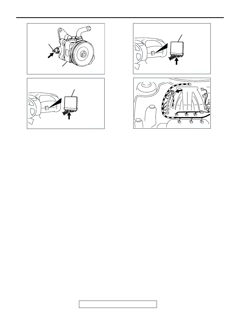
CONNECTOR: B-19
POWER
STEERING
PRESSURE
SWITCH
POWER STEERING
OIL PUMP
AB
B-19
AK300244
CONNECTOR: C-55 <A/T>
AG
PCM
C-55 (GR)
AK300091
CONNECTOR: C-58 <M/T>
ECM
AC
C-58 (GR)
AK300087
CONNECTOR: B-47
AB
B-47 (B)