Mitsubishi Eclipse. Manual - part 503


  Index      Mitsubishi     Mitsubishi Eclipse - service repair manual 2004 year


Search            


Content   ..  501  502  503  504   ..


Mitsubishi Eclipse. Manual - part 503


MULTIPORT FUEL INJECTION (MFI) DIAGNOSIS

TSB Revision

MULTIPORT FUEL INJECTION (MFI) <3.0L>

13B-555

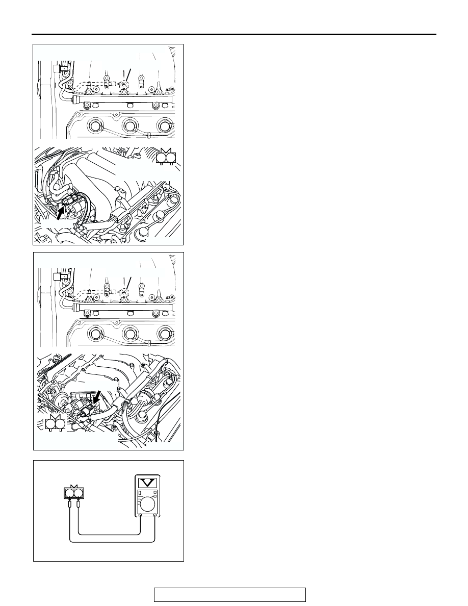
(1) Disconnect the knock sensor connector B-35.
(2) Start the engine and run at idle.

(3) Measure the voltage between knock sensor side connector 

terminal No. 1 (output) and No. 2 (ground).

(4) Gradually increase the engine speed.

• The voltage increases with the increase in the engine 

speed.

(5) Turn the ignition switch to the "LOCK"(OFF) position.
Q: Is the sensor operating properly?

YES : Replace the ECM or PCM. Then go to Step 6.
NO :  Replace the knock sensor. Then go to Step 6.

AK300444

1

2

AB

B-35 (GR)

CONNECTOR: B-35 <WITHOUT INTAKE 
MANIFOLD TUNING  SYSTEM>

KNOCK SENSOR

HARNESS 
CONNECTOR:
COMPONENT SIDE

AK300749

1

2

KNOCK SENSOR

CONNECTOR: B-35 <WITH INTAKE 
MANIFOLD TUNING  SYSTEM>

AB

B-35 (GR)

HARNESS CONNECTOR:
COMPONENT SIDE

AK103514AB

KNOCK SENSOR
SIDE CONNECTOR

1 2

MULTIPORT FUEL INJECTION (MFI) DIAGNOSIS

TSB Revision

MULTIPORT FUEL INJECTION (MFI) <3.0L>

13B-556

STEP 6. Using scan tool MB991958, read the diagnostic 
trouble code (DTC).

CAUTION

To prevent damage to scan tool MB991958, always turn the 
ignition switch to the "LOCK"(OFF) position before con-
necting or disconnecting scan tool MB991958.
(1) Connect scan tool MB991958 to the data link connector.
(2) Turn the ignition switch to the "ON" position.
(3) Erase the DTC.
(4) Test drive under the following conditions:

• Engine speed: 3,000 − 5,000 r/min

• Engine load: 40 % or more

• Drive a minimum of 3 seconds after the above condi-

tions have been met.

(5) After completing the test drive, read the DTC.Turn the 

ignition switch to the "LOCK"(OFF) position.

Q: Is DTC P0325 set?

YES : The inspection is complete.
NO :  Retry the troubleshooting.

AK300810

AB

MB991911

16-PIN

MB991827

MB991824 

MULTIPORT FUEL INJECTION (MFI) DIAGNOSIS

TSB Revision

MULTIPORT FUEL INJECTION (MFI) <3.0L>

13B-557

DTC P0335: Crankshaft Position Sensor Circuit

AK101608

1 2

3

RED

-

WHITE

RED

-

WHITE

RED

-

WHITE

RED

BROWN

GREEN-

RED

BATTERY

MFI
RELAY

CRANKSHAFT
POSITION
SENSOR

     B-20
MU802603

43 <M/T>*2
45 <A/T>*4

34 <M/T>*1
16 <A/T>*3

4

1

2

3

3

1

2

5 V

ENGINE CONTROL 
MODULE (ECM) <M/T>
OR
POWERTRAIN CONTROL
MODULE (PCM) <A/T>

65

43
50

42
49

41
48
60 61

64

46 47
58 59
67 68

45

56
66

52

51

44

53

62

54

63

57

55

C-58 <M/T>
(MU803782)

C-55 <A/T>
(MU803781)

42 43
48 49 50 51 52 53 54 55 56 57

46

45

44

58 59

60 61 62 63

64 65 66

47

41

Crankshaft Position Sensor Circuit

NOTE
*1: ECM connector C-51 <M/T>
*2: ECM connector C-58 <M/T>
*3: PCM connector C-52 <A/T>
*4: PCM connector C-55 <A/T>

C-51 <M/T>, C-52 <A/T>
         (MU803784)

2

3 4

5 6

7 8

9

11 12 13 14 15 16 17 18 19 20

30

21 22 23

24 25

26 27 28 29

3132 33

34 35

1

10

3 4

1 2

A-18X

MULTIPORT FUEL INJECTION (MFI) DIAGNOSIS

TSB Revision

MULTIPORT FUEL INJECTION (MFI) <3.0L>

13B-558

.

CIRCUIT OPERATION

• The crankshaft position sensor power is supplied 

from the MFI relay (terminal No. 4).

• Terminal No. 1 of the crankshaft position sensor 

is grounded with ECM (terminal No. 34) <M/T> or 
PCM (terminal No. 16) <A/T>.

• A 5-volt voltage is applied on the crankshaft posi-

tion sensor output terminal (terminal No. 2) from 
the ECM (terminal No. 43) <M/T> or PCM (termi-
nal No. 45) <A/T>. The crankshaft position sen-
sor generates a pulse signal when the output 
terminal is opened and grounded.

.

TECHNICAL DESCRIPTION

• The crankshaft position sensor detects the crank 

angle (position) of each cylinder, and converts 
that data to pulse signals, which are then input to 
the ECM <M/T> or PCM <A/T>.

• When the engine is running, the crankshaft posi-

tion sensor outputs a pulse signal.

• The ECM <M/T> or PCM <A/T> checks whether 

pulse signal is input while the engine is cranking.

.

AK300110

CRANKSHAFT
POSITION
SENSOR

CONNECTOR: B-20 <WITHOUT INTAKE 
MANIFOLD TUNING  SYSTEM>

AB

B-20 (B)

AK300111

CONNECTOR: B-20 <WITH INTAKE 
MANIFOLD TUNING  SYSTEM>

AB

B-20 (B)

CRANKSHAFT
POSITION
SENSOR

AK300244

CONNECTORS: C-52, C-55 <A/T>

AB

PCM

C-52 (GR)

C-55 (GR)

AK300091

CONNECTORS: C-51, C-58 <M/T>

ECM

AB

C-51 (GR)

C-58 (GR)

AK300121

MFI RELAY

CONNECTOR: A-18X

AB

A-18X


Content   ..  501  502  503  504   ..